Filter: Safe | Mon, May 4, 7:38 PM CDT

Renderosity Forums / Cinema 4D


Welcome to the Cinema 4D Forum

Forum Moderators: CHMedia Forum Coordinators: Kalypso

Cinema 4D F.A.Q (Last Updated: 2024 Aug 27 11:07 am)

C4D Gallery Speed Modeling Sessions C4D Freestuff
 
 
Checkout the Renderosity MarketPlace - Your source for digital art content!


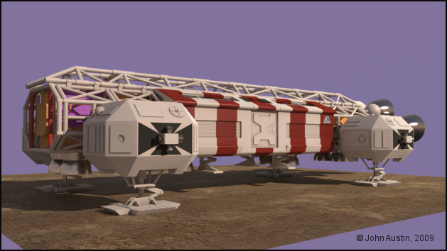
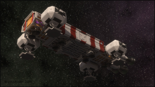
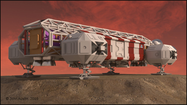
Subject: Space 1999 - Project Eagle - A 3D Model In The Making


Becco_UK ( ) posted Thu, 07 May 2009 at 5:24 PM

Mandrake7062: Polygon selections are your friend with BodyPaint! Especially with a detailed model such as these Eagles.


Mandrake7062 ( ) posted Thu, 07 May 2009 at 5:30 PM

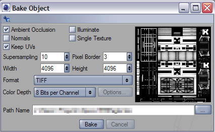
Ahh, Totally forgot about assigning those for painting..
So you can make a few extra cuts, and even though you adding some polys it's just tag tag tag and paint.

I'm pretty think sometimes, I follow Wolfgang's tut and he talked about that and bing, in one ear and out the other. That's why I need to practice practice practice!!!


Becco_UK ( ) posted Thu, 07 May 2009 at 5:53 PM · edited Thu, 07 May 2009 at 5:56 PM

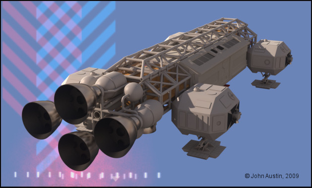
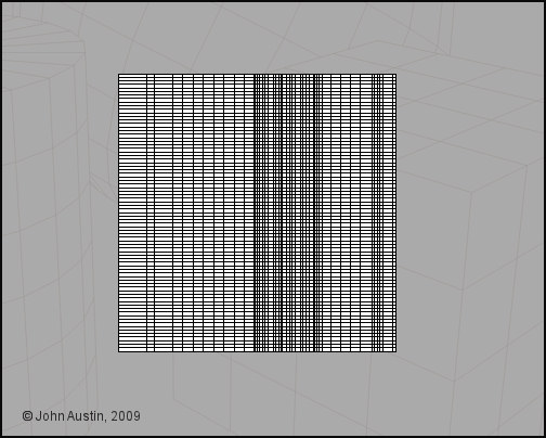
Mandrake7062: Well, you shouldn't really have to add cuts to make polygon selections. Most time I complete a sub assembly and make as many polygon selections that I think will be needed for UV mapping in Bodypaint. ie: each of the Eagle side pods has over 50 polygon selection tags. Time used making them is more than offset when UV mapping.

This aircraft tutorial by Bazze is great for anyone wishing to get the basics of Bodypaint - the only thing missing is using the relax tool (when required) but that's easy enough to get the hang of.


Becco_UK ( ) posted Fri, 08 May 2009 at 4:18 AM

I forgot to post the link to Bazzes' tutorials! http://www.colacola.se/wip_p47.htm


Becco_UK ( ) posted Fri, 08 May 2009 at 10:10 AM

file_430443.jpg

**contrafibbularities**: I had a mess with Maxwells' light scattering and glare settings and managed to recreate the effect of the in-progress render but with the finished model. Large image in my Gallery.


Becco_UK ( ) posted Sun, 10 May 2009 at 4:54 AM

file_430548.jpg

The spine took a few days to UV map but I got there in the end with a nice UV to use when the proper painting starts. As with other parts of this model I also baked an ambient occlusion that is being used as a 'dirt' control mask in my paint software.


Becco_UK ( ) posted Sun, 10 May 2009 at 4:54 AM

file_430549.jpg

All of the Eagle so far.


Mandrake7062 ( ) posted Sun, 10 May 2009 at 3:34 PM

That's a cool render with the cross hatching background. :)


Becco_UK ( ) posted Wed, 13 May 2009 at 10:25 AM

file_430756.jpg

Returning to the passenger pod it's seen here with all the different parts connected and some polygon selection tags created - 46 of them. Time spent making polygon selection **is** rewarded in Bodypaint by creating the UV faster, distortions minimised and as seam free as posible. Still tedious work though!


Becco_UK ( ) posted Wed, 13 May 2009 at 10:27 AM

file_430757.jpg

After the UV is made it's time to bake an Ambient Occlusion - for use as a dirt mask layer in my paint software.


Becco_UK ( ) posted Wed, 13 May 2009 at 10:29 AM

file_430758.jpg

The passenger pod with a 'dirt' layer - this dirt layer is flexible to use both in terms of colour and opacity. Always seems much better to use Cinemas' Ambient Occlusion in this manner.


Becco_UK ( ) posted Wed, 13 May 2009 at 10:32 AM

file_430759.jpg

The advantage of spending time making a nice UV map is also rewarded when texture adjustments are required - in this example it was simple to add some stripes to make a rescue/medical pod variant.


Mandrake7062 ( ) posted Wed, 13 May 2009 at 10:37 AM

Beauty!!


Becco_UK ( ) posted Wed, 13 May 2009 at 10:37 AM · edited Wed, 13 May 2009 at 10:38 AM

file_430760.jpg

Still with the passenger pod I thought I would make an Alpha Moonbase logo. This started with a photo of a logo from a real Eagle model. That image was then used as a background to trace out a new logo using a mixture of vectors and hand painting. I'm not after a perfect look but something that will look realistic at the most important time - the render! I made the logo in mono' to use it as mask over more suiatble colours.


Becco_UK ( ) posted Wed, 13 May 2009 at 10:55 AM · edited Wed, 13 May 2009 at 10:58 AM

file_430762.jpg

The 'final' version of the logo, scaled down in dimensions to fit the passenger pod texture map. The positioning of the logo on the passenger pod was helped by using a photograph of an early Eagle model. As already mentioned I'm not interested in a pixel perfect logo but one that looks realistic when rendered.


Becco_UK ( ) posted Wed, 13 May 2009 at 3:17 PM

file_430780.jpg

A render of the story so far.


Becco_UK ( ) posted Wed, 13 May 2009 at 3:21 PM

file_430781.jpg

A different angle.


Becco_UK ( ) posted Wed, 13 May 2009 at 3:29 PM · edited Wed, 13 May 2009 at 3:30 PM

file_430782.jpg

The engine 'bells' were only made roughly so now they will be finished. My original construction of each bell has four parts - a connection peice, outer bell surface, inner bell surface and the Saturn V model kit part.

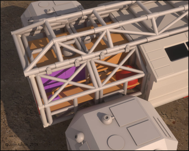
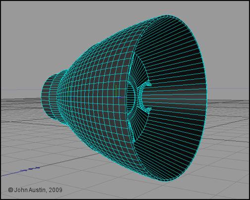
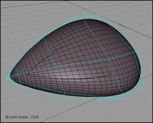
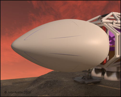
The outer 'bell' surface was made from two lathed b-splines. I find this type of spline for obtaining a nice curve with just three control points. I find that bezier splines are not that satisfactory for making these engine 'bells'. A few extra steps are required using my method but the final result will speak for itself.


Becco_UK ( ) posted Thu, 14 May 2009 at 5:03 AM

file_430803.jpg

Grooves cut into the engine bell using mainly loop knife cuts and negative extrude of selected polygons. Each edge has a low value bevel applied.


Becco_UK ( ) posted Thu, 14 May 2009 at 5:29 AM · edited Thu, 14 May 2009 at 5:36 AM

file_430804.jpg

Because of cutting grooves into If the bell the UV's would be very messy and tidying them up in Bodypaint would waste time, plus I find UV mapping tedious at the best of times. So a solution is to select edges as shown.


Becco_UK ( ) posted Thu, 14 May 2009 at 5:52 AM

file_430805.jpg

To generate a new spline, Cinemas' **Edge To Spline** tool is used. Check that the new spline has a smooth colour graduation - this ensures that later UV's will be in order.


Becco_UK ( ) posted Thu, 14 May 2009 at 6:21 AM

file_430806.jpg

The new engine 'bell' spline lathed. A quick check of seeing if the UV's are in order is to apply a checker material and have a play with the tile settings. The checkers should move across the surface without sudden breaks in the checker pattern.


Becco_UK ( ) posted Thu, 14 May 2009 at 6:49 AM

file_430807.jpg

A 2048*2048 texture map is being used for the 'bell' and a quick check in Bodypaint shows nicely arranged UV's with no further UV work required. The bell is a conical shape and UV's created this way will have some distortion - this could be fixed by scaling selected UV's but the engine bell I've made will have no detailed texturing so I'm happy to leave as is.


Becco_UK ( ) posted Thu, 14 May 2009 at 7:07 AM

file_430809.jpg

Ambient Occlusion baked for to use as a texture 'dirt' mask  and a weight map in a Maxwell Render material.


Becco_UK ( ) posted Thu, 14 May 2009 at 10:56 AM

file_430824.jpg

The new engine 'bell' with a *simple* 2 layer Maxwell Render material applied. As with the previous 'bell' most of the material is using Platinum IOR data to power the metal effect with my Ambient Occlusion map used as a weight map to add some 'dirt' into the grooves.

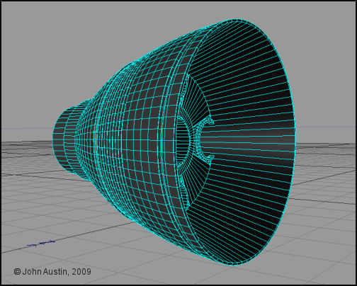
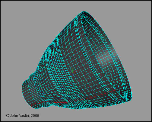
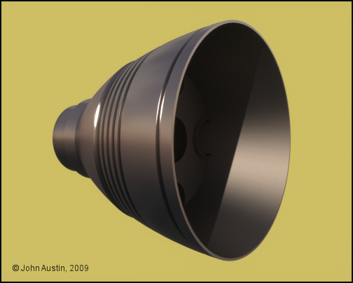
The inner 'bell' surface was remade in the same manner as the new outer 'bell' surface.


Becco_UK ( ) posted Thu, 14 May 2009 at 3:14 PM · edited Thu, 14 May 2009 at 3:20 PM

file_430849.jpg

The singe engine bell assembly turns into 4! The 3 duplicates where made using Cinemas' instancing tool which in turn are converted to **true instances** by Maxwell Render at render time - thus saving total polygons. I ended up with an higher poly count structure with less impact on system resources - to the tune of about 15,000 less polygons at render time.


Becco_UK ( ) posted Fri, 15 May 2009 at 11:29 AM

file_430908.jpg

Eye rest day today so all I done with the Eagle was render it in a more space type environment to see how the materials looked. I'm mostly happy with them and maybe a touch more reflectivity would make the Eagle even nicer.


Becco_UK ( ) posted Fri, 15 May 2009 at 6:40 PM

file_430942.jpg

Same environment, different angle.


Becco_UK ( ) posted Sat, 16 May 2009 at 9:55 PM · edited Sat, 16 May 2009 at 9:55 PM

file_430986.jpg

I've decided to do some texture work on all the side pods and landing gear, this is one at the start.


Becco_UK ( ) posted Sat, 16 May 2009 at 10:00 PM

file_430987.jpg

Here the landing gear has been slightly darkened and a few of the details textured. All the landing framework includes a small percentage of Iron IOR data in the Maxwell material. Using Bodypaint some panel shading work gets underway. This is where spending time preparing UV maps is rewarded with the ability to paint distortion free detail,


Becco_UK ( ) posted Thu, 21 May 2009 at 3:42 AM · edited Thu, 21 May 2009 at 3:43 AM

file_431210.jpg

On top of this Eagles' walkways are some Lunar Module parts from the Airfix Apollo Saturn V model kit. I've measured the overall dimensions of those parts and made digital 3d versions. Some detail has been left out of those parts because they are tucked in amongst the cages/spine framework and are not readily visible.

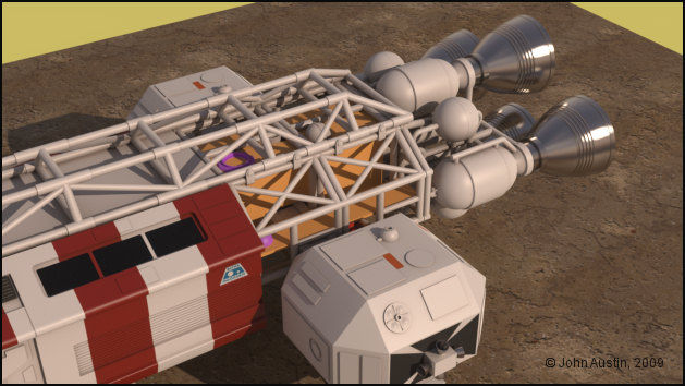
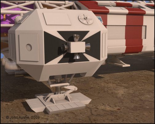
A panel from the Tamiya Leopard kit has also been made and added to the side of the front walkway.

Various pipe valves have also been added.


Becco_UK ( ) posted Thu, 21 May 2009 at 3:47 AM

file_431211.jpg

The newly added detail mostly gets hidden in full renders of the Eagle!


Becco_UK ( ) posted Thu, 21 May 2009 at 12:39 PM · edited Thu, 21 May 2009 at 12:40 PM

file_431237.jpg

The Command Module gets underway with simple 3 polygon guides, the corners of which correspond to the corners of Command Module windows/black area.


Becco_UK ( ) posted Fri, 22 May 2009 at 4:21 AM · edited Fri, 22 May 2009 at 4:23 AM

file_431299.jpg

Curves have now been added to the window/black edges. Cinema4D *B Splines* (each with three points) were used to form the curves. I find *B splines* are ideal for replicating the curves that feature in these type of models.

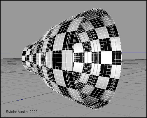
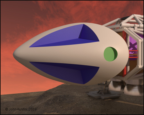
I'm making those surfaces first and then forming a Cinema4D's hypernurbs to fit rather than cut the window/black areas out of an hypernurbs. The curved edges are particularly useful in helping the overall shape of the command module to be accurate.


Mandrake7062 ( ) posted Fri, 22 May 2009 at 5:39 AM

Nice sky too! Looks just like the show.


contrafibbularities ( ) posted Fri, 22 May 2009 at 8:59 AM

Very nice!

Very informative, too, which is very much appreciated! I must remember that "edge to spline" trick. Simple but effective to get those UVs from the modified bells.

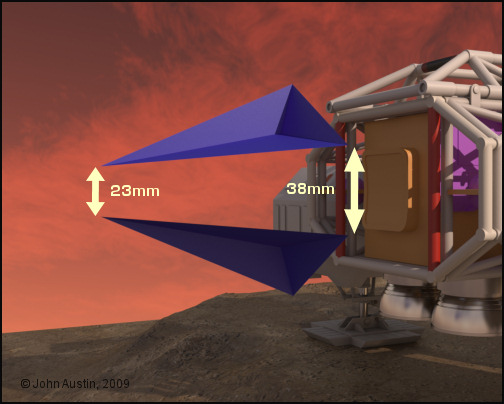
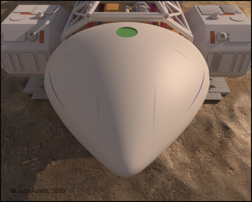
I'd like to learn a bit more about the way you are modeling the command capsule, your approach sounds both interesting and useful for building objects like these. That first screenshot shows simple polygon objects defining the rough shape, right?

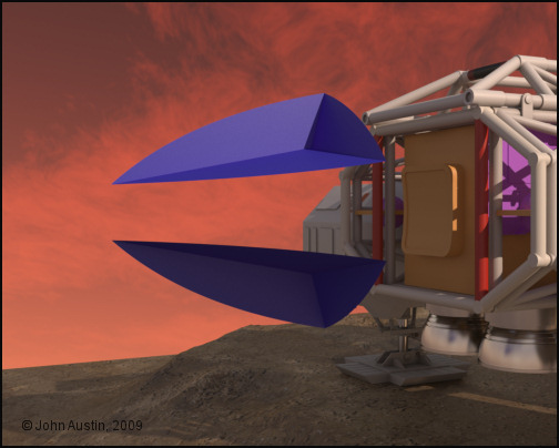
You say that you then used B splines to create the actual curves. I'm not quite sure how exactly you do that to get the shape shown in the second screenshot. Do you build a spline cage to get that object? Could you describe that part in more detail, and maybe post a couple more explanatory screenshots? 

Cheers,
contrafibbularities


Becco_UK ( ) posted Fri, 22 May 2009 at 9:10 AM · edited Fri, 22 May 2009 at 9:12 AM

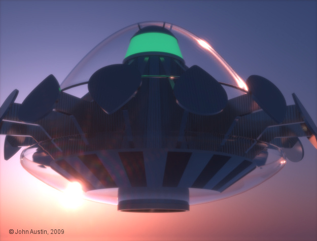
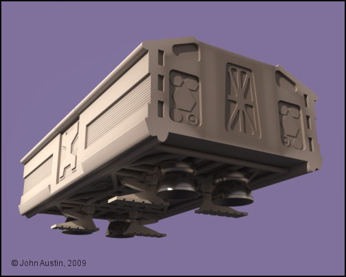
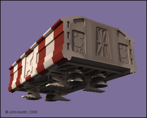
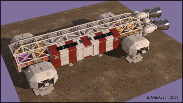
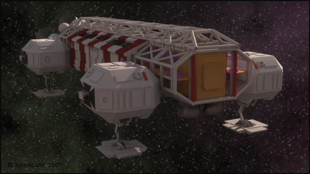
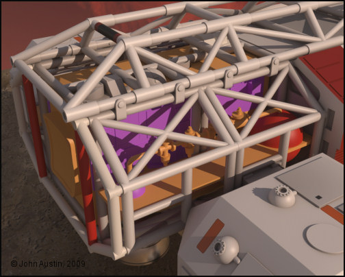
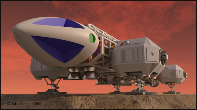
Mandrake: Thank you. Looks like a better version of that red sky will feature in a proper render. You've probably noticed that reflections do not match the sky. That's because I'm using another image for reflections and refraction and it doesn't seem worth changing the setup for preview renders.

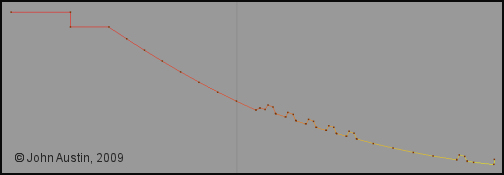
contrafibbularities: The edge to spline is very useful - when selected (in point mode) the new spline should have a smooth colour graduation. If it doesn't a quick optimise usually sorts things out.

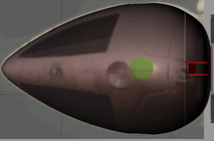
The window area rough object is my main part for the command module :-) Without the overall dimensions being accurate then the whole command module will fail. Those added curves are easier to do than explain but hopefully over the weekend I will be able to do a 'brief' description of the process - it's a bit more involved than using a hypernurbed plane (for instance) but I found trying this has given me more accuracy with points where I wish them to be rather than hypernurbs running the show. 


contrafibbularities ( ) posted Fri, 22 May 2009 at 9:34 AM

Becco
Please do take your time. If you don't have the time, or the patience, I understand. It's just that people hardly ever present their projects the way you do. Threads like these are a great source of learning, and I can't help but bug you a bit and tap into that source, if possible. :-)

Cheers,
contrafibbularities


Mandrake7062 ( ) posted Fri, 22 May 2009 at 9:37 AM

Ohhhhh Point mode, that's why I failed to get a gradient...


Becco_UK ( ) posted Sat, 23 May 2009 at 4:41 AM · edited Sat, 23 May 2009 at 4:46 AM

file_431377.jpg

**contrafibbularities**: I will do the 'curve' outline once I see if the idea works in obtaining an accurate Command Module!

Mandrake7062: Yes, have a look at a spline in point mode and you will see it is coloured. For making problem free UV maps, from a lathed spline, the colour graduation should look smooth. If it doesn't try optimising the new spline. If that doesn't do the trick optimise the base mesh before using edge to spline. Broken colour graduation usually come about when a model is formed from several parts. As always, it's easier to do than write about.

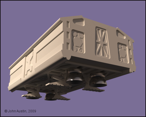
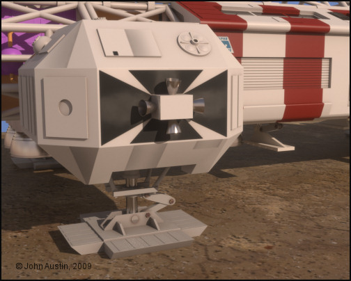
Back to the Command Module a couple of modified cubes inside a HyperNURBS are being used to form the overall front and rear shapes. Control points are kept to a minimum which helps in creating a bump free mesh. Points are moved about so that the mesh fits the window area.


Becco_UK ( ) posted Sat, 23 May 2009 at 4:44 AM

file_431379.jpg

This is how the rough start Command module looks so far - still a long way to go!


Becco_UK ( ) posted Sun, 24 May 2009 at 3:21 AM

file_431414.jpg

To further assist in getting the curves of the HyperNURB mesh as close as possible (before making it editable) I've cut some dummy sensor dishes into it. The 'window' area protruding through the main command mudule mesh is about 0.5mm at it widest point. That could be fixed by adding a loop knife cut around my low poly control mesh but doing so would add many more polygons. So, Ive decided to get the HyperNurbs mesh as close as possible, make it editable and refine 'by hand'.


Mandrake7062 ( ) posted Sun, 24 May 2009 at 6:15 PM

Seems a bit pinched up front Becco. Maybe slide that third control line back and add one more.
Pull them out a bit. 
The hardest shape I've ever worked on.


Becco_UK ( ) posted Sun, 24 May 2009 at 6:22 PM

Mandrake7062: Thank you. The overall dimension is very accurate - it still has to have the panelling added so that will change its appearance. The window guide I made is making this easy enough to do but I've had an idle day today :-)


Becco_UK ( ) posted Sun, 24 May 2009 at 7:10 PM

file_431451.jpg

**Mandrake7062**: Photo's are always a good rough check of dimensions. Here an Eagle command module has been overlaid onto my 3d mesh - looks fine to me (taking into account the photo's perspective distortion).

Those plans that Chris once linked too are not that accuarate in some areas - all my mesh has been developed from the Season 1 plans and measurements direct from actual kit parts.


Mandrake7062 ( ) posted Sun, 24 May 2009 at 7:14 PM

Yes looks good, you know I got so tuned in on the II, and I think the shape is a bit different.


Becco_UK ( ) posted Sun, 24 May 2009 at 7:28 PM

file_431452.jpg

**Mandrake7062**: The main thing being that it ends up looking like an Eagle! I tried a side photo' as a rough check and that looks ok too. I hope to cut the window/black area out tomorrow and some mesh around the sensor dishes will need tweaking by hand.

If this command module turns out as I wish it too then it will be 3d printed to form the basis of a proper mould for a command module.

I will more than likely end up with two meshes - one for 3d printing and one for this Cinema made Eagle.


...Time.Bandit... ( ) posted Mon, 25 May 2009 at 3:33 AM

Definitly the longest work in progress thread ever!


................................................................................................
Randall
: Look, do you want to be leader of this gang?
Strutter: No, we agreed: No leader!
Randall: Right. So shut up and do as I say. - Time Bandits .1981


Becco_UK ( ) posted Mon, 25 May 2009 at 5:05 PM

file_431525.jpg

**...Time.Bandit...**: It's only just getting started :-)

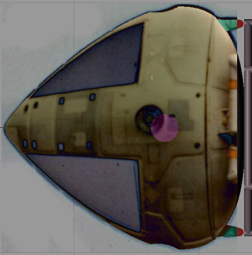
Now the Window/Black area has been cut out of the command module mesh and all the edges where the cuts were have been tidied up by hand. The mesh is about 1mm out in one part so that will be adjusted before the panelling gets added. This particular mesh will be the one used for 3d printing and another version with details made for this 3d Eagle.


Becco_UK ( ) posted Tue, 26 May 2009 at 12:52 AM

file_431569.jpg

Another view.


Privacy Notice

This site uses cookies to deliver the best experience. Our own cookies make user accounts and other features possible. Third-party cookies are used to display relevant ads and to analyze how Renderosity is used. By using our site, you acknowledge that you have read and understood our Terms of Service, including our Cookie Policy and our Privacy Policy.