Filter: Safe | Fri, May 1, 5:33 AM CDT

Renderosity Forums / Cinema 4D


Welcome to the Cinema 4D Forum

Forum Moderators: CHMedia Forum Coordinators: Kalypso

Cinema 4D F.A.Q (Last Updated: 2024 Aug 27 11:07 am)

C4D Gallery Speed Modeling Sessions C4D Freestuff
 
 
Checkout the Renderosity MarketPlace - Your source for digital art content!


Subject: Space 1999 - Project Eagle - A 3D Model In The Making


Becco_UK ( ) posted Tue, 24 March 2009 at 4:55 PM · edited Thu, 30 April 2026 at 7:09 PM

The Eagle Transporter from Gerry Andersons'  Space 1999 TV series is the subject of this project.

Reference material has included viewing many online photographs, most notably the ones of the Eagle One restoration by David Sissons at http://www.smallartworks.ca/Articles/Restoration/Restore1.html

To assist accuracy, blueprints at http://www.smallartworks.ca/PS/Space1999/ChrisTrice/Blueprints/Blueprints.html by Daniel Prud'homme and Chris Trice were purchased. Those drawings will also be used in the future to help with constructing a 44" real model.

Information at the Eagle Transporter forums http://www.eagletransporter.com/forum/index.php has is an invaluable resource.

Main modelling software being used is Cinema4D 9.6 with Maxwell Render http://www.maxwellrender.com/ being used for rendering.


Becco_UK ( ) posted Tue, 24 March 2009 at 5:06 PM

file_427057.jpg

I decided making the 'spine' would be a good place to start, although with 3d models the starting point is not always relevant. The 'spine' on the real model consists of soldered joints and 3d pipes poking through each other never seem to have a correct 'feel'. So, making use of Jürgen Meier pipe joining plugins and tutorials by **contrafibbularities** some joined parts were made.


Becco_UK ( ) posted Tue, 24 March 2009 at 5:10 PM

file_427058.jpg

A section of the spine is made. The white part is a single mesh. The red parts are 'poked' through - it would have been nice to make every joint properly but polygon count would have got to high, especially so as the model progresses.


Becco_UK ( ) posted Tue, 24 March 2009 at 5:11 PM · edited Tue, 24 March 2009 at 5:13 PM

file_427059.jpg

The completed spine, made as accurate as possible. The joined pipes should make UV mapping and painting a little less time consuming later.


Mandrake7062 ( ) posted Tue, 24 March 2009 at 5:20 PM

Very nice Becco, those are the two pipes I've been leaning towards joining, the rest, not so much.. It should not affect poly count. Looks just fine.


Becco_UK ( ) posted Tue, 24 March 2009 at 5:26 PM · edited Tue, 24 March 2009 at 5:27 PM

file_427060.jpg

**Mandrake7062**: Thank you - it is the season of Eagle models!

The 'cages' were the next components to be tackled. I used a very simple 3d model to help align the pipe work. The measurements of the part  were taken directly from the blueprints.


Becco_UK ( ) posted Tue, 24 March 2009 at 5:28 PM · edited Tue, 24 March 2009 at 5:30 PM

file_427061.jpg

More more pipe joints made and positioned.


Becco_UK ( ) posted Tue, 24 March 2009 at 5:45 PM · edited Tue, 24 March 2009 at 5:47 PM

file_427062.jpg

Joining the joints! The new blue colour are joined sub components that are then 'poked' though the white single mesh. Not strictly one 'white; mesh though because the 'cages' are made in two halves which replicates the real Eagle model.


Mandrake7062 ( ) posted Tue, 24 March 2009 at 5:45 PM

As long as your at it, lets see a close up of one of the angled ones, been thinking about them on and off.


Becco_UK ( ) posted Tue, 24 March 2009 at 5:52 PM

file_427064.jpg

**Mandrake7062**: I will post an image of an angled part later. Those took longer because the joins overlapped each other and had to be tidied up 'by hand'.

The 'cages' positioned on the spine - the rear 'cage' is a copy of the front one.


Mandrake7062 ( ) posted Tue, 24 March 2009 at 5:58 PM

Yes, that must be a bit tricky. looks great, got your plan, ay?


Becco_UK ( ) posted Tue, 24 March 2009 at 6:32 PM · edited Tue, 24 March 2009 at 6:33 PM

Mandrake7062: Yes. the drawings arrived about a week ago. I haven't found a need to scan any parts of them at present for my 3d model - just measure the part on the drawng and make the 3d model the same size in Cinema4D. I've started the walkways and shelves but still have to wait for some old plastic kits so that some detail can be replicated in 3d. Plenty of other parts that can be done though.


Mandrake7062 ( ) posted Tue, 24 March 2009 at 6:42 PM

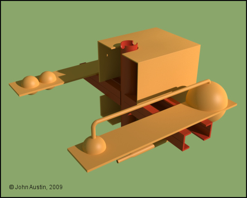
Nice, might one of those be the two packages above the side door? On the roof. Looks like a double row of cylinders one row long on row shorter. Can't tell really.

My dimension will be off as I'm running this right from the print. Shh, don't tell Daniel
I could go the other route but I'm just to keen to model, that I'd rather be off as I'm having fun!.


Becco_UK ( ) posted Tue, 24 March 2009 at 6:49 PM

Mandrake7062: The parts you mention come from the Revell 1/24 scale Gemini kit - took me a few months to get one of those at a price I was happy with. I will do some photos' and measurements to share with you - I just wasn't in the mood for taking photos today!


Mandrake7062 ( ) posted Tue, 24 March 2009 at 6:54 PM

No problem, this will be on the board for a while. hehe Thanks.


Becco_UK ( ) posted Wed, 25 March 2009 at 4:32 AM · edited Wed, 25 March 2009 at 4:34 AM

file_427082.jpg

As requested, here's a couple of pipework renders.


Becco_UK ( ) posted Thu, 26 March 2009 at 7:19 AM

file_427154.jpg

Inside each cage is a walkway and shelves with plastic kit detailing. This is the start of the front walkway.


Mandrake7062 ( ) posted Thu, 26 March 2009 at 7:38 AM

Thanks Becco, I need to follow your lead on this as I tried to study the reference pics last night and I can't see the shelf to well, I was going to consult the Eagle 1 prints tonight.


Becco_UK ( ) posted Thu, 26 March 2009 at 8:17 AM

Mandrake7062: Dont follow too close! Although the overall structure and dimensions of the walkways and shelves are the same it is the kit detail that is greatly different on the version you are making.


contrafibbularities ( ) posted Thu, 26 March 2009 at 2:20 PM

Oh, cool, another Eagle. 😄

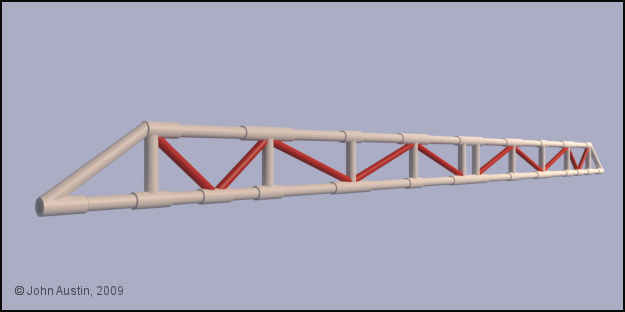
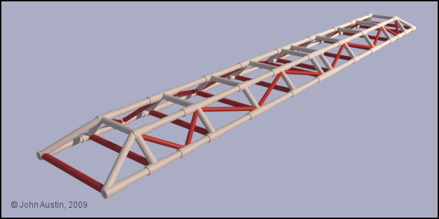
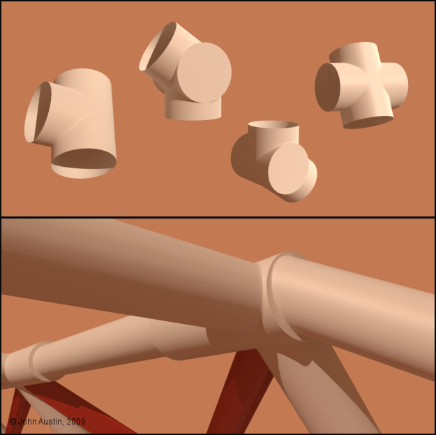
Great project presentation, Becco, very informative, too! That cage is looking very good. I love the look of those joined pipes, of course. It's definitely worth soldering them together, it'll pay off when you'll do close-up renders of the finished model. I'm looking forward to seeing your progress with the Eagle!

Cheers
contrafibbularities


Becco_UK ( ) posted Thu, 26 March 2009 at 4:00 PM · edited Thu, 26 March 2009 at 4:00 PM

file_427190.jpg

**contrafibbularities**: Thank you. Your recent tutorial helped such a lot in joining the pipes fairly quickly. I had been researching this model since last year and had been thinking how to join all the pipework - then along came the 'pipe' joining plugin and your tutorial!

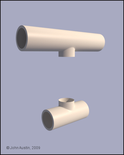
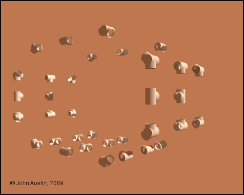
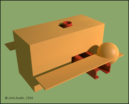
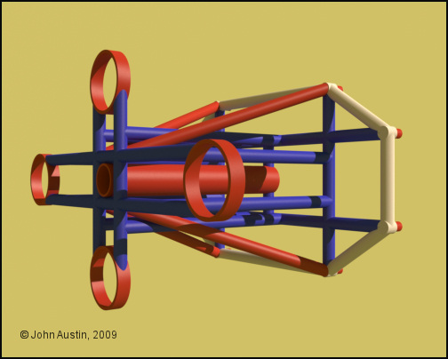
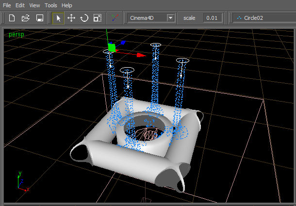
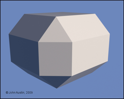
Here some detail starts to get added to the front walkway. Half of it is hidden from the render to depict the basic construction of the real model. Cinema hemispheres and cylinders were used for the shelf parts. There are still some valves and other fittings to be added but I'm still sorting out a supplier of the rael components before I make the 3d ones. This is one of the reasons for colour coding assemblies - I can see at a glance what sections have to be worked on without making endless notes!

Tomorrow I hope to start reproducing some detail from a 1970's Tamiya M551 Sheridon tank that is fitted to the walkways. 


Becco_UK ( ) posted Tue, 31 March 2009 at 4:09 AM

file_427538.jpg

Some purple coloured details start to get added to the walkways. I have models that have these parts so using a digital caliper, accuracy is fairly high. On the model plastic parts there are grills and rivets but to keep poly' count down a bump map will be used to replicate such detail.


Becco_UK ( ) posted Tue, 31 March 2009 at 4:12 AM

file_427539.jpg

The walkways have been put to one side for the time being and the engines framework is being made. The blue framework is all one mesh with properly joined pipes.


Becco_UK ( ) posted Tue, 31 March 2009 at 4:13 AM

file_427540.jpg

A different view of the engines framework.


Becco_UK ( ) posted Tue, 31 March 2009 at 6:52 PM

file_427596.jpg

Some engine parts start to get fitted to the framework. Connected and welded Cinema4D cylinder and hemispere primitives made up the larger components.


Becco_UK ( ) posted Thu, 02 April 2009 at 8:00 PM

file_427760.jpg

A set of pipes that detail the engine assembly. Each pipe has joined connections.


Becco_UK ( ) posted Fri, 03 April 2009 at 2:36 AM · edited Fri, 03 April 2009 at 2:37 AM

file_427791.jpg

The new engine assembly. Engine 'bells' are to be finalised when I can get to see more reference material of the grooves cut into them.


Mandrake7062 ( ) posted Fri, 03 April 2009 at 4:37 AM

So that's what you've been doing, must have missed a notification here.
Look so clean!


Becco_UK ( ) posted Fri, 03 April 2009 at 6:11 AM

file_427799.jpg

**Mandrake7062**: Yes, the engine assembly kept me busy for a while! Lots of polygons in this component. I estimate the final model will have about 400,000 polygons but I will be happy up to 500.000. I'm tempted to also make a lower poly' spine spine and cages but will decide about that another time.

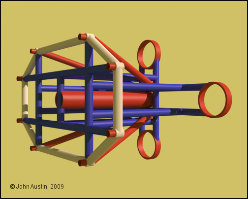
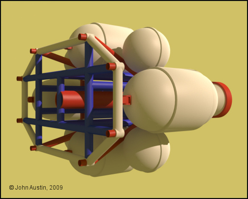
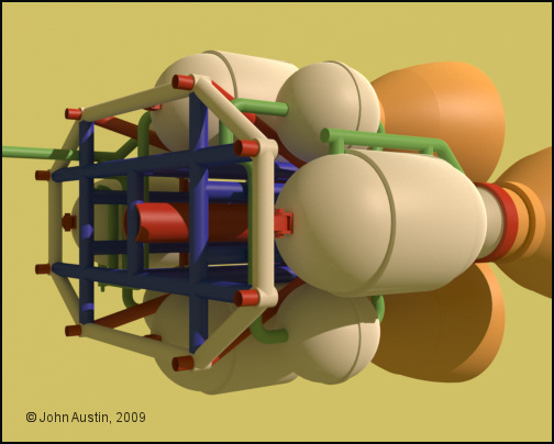
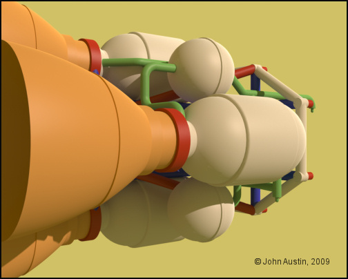
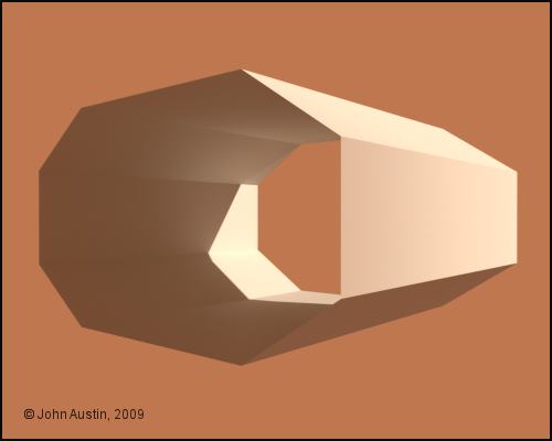
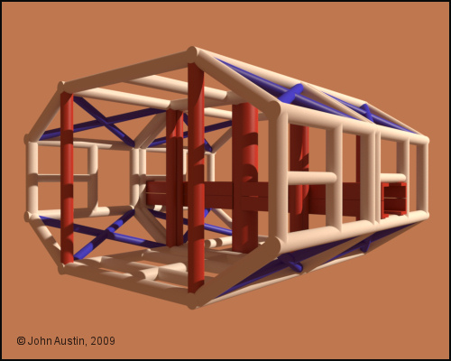
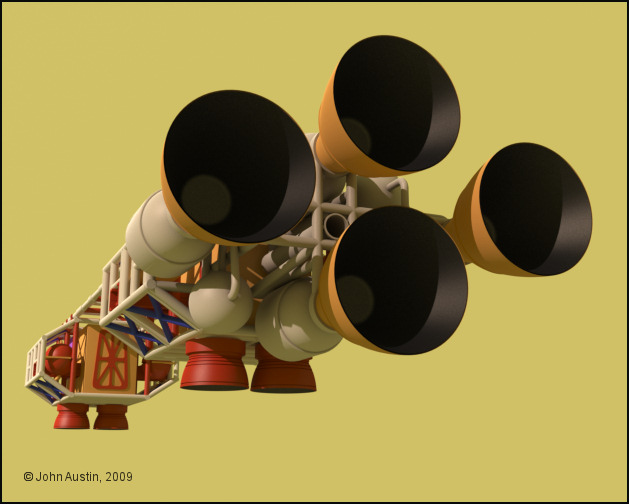
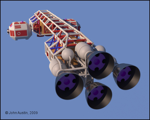
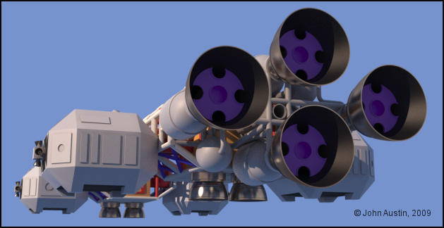
Rear view of the engine assembly. The large tanks have been slightly modified including adding grooves so that the top and bottom ones clear the framework.


Becco_UK ( ) posted Sat, 04 April 2009 at 8:48 AM

file_427897.jpg

One of the rear joints looks odd without some 'solder'. So using Realflow a section of the mesh is used for some 'solder' particles to interact with.


Becco_UK ( ) posted Sat, 04 April 2009 at 10:15 AM

file_427907.jpg

The meshed Realflow 'solder' particles. All the engine assembly is ready for painting now.


contrafibbularities ( ) posted Sat, 04 April 2009 at 11:03 AM

Wow, Becco, this is one hell of a construction! Great work!

Cheers
contrafibbularities


Becco_UK ( ) posted Sun, 05 April 2009 at 12:57 PM

file_428017.jpg

**contrafibbularities**: Thank you. Now you can see the results of your pipe joining tutorial!

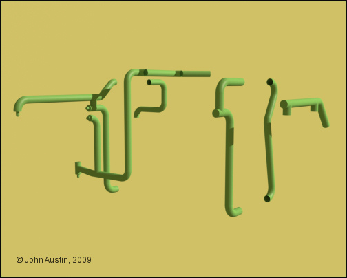
The first attempt using Realflow for the 'soldered' joint at the rear of the engine assembly, turned out a bit blobby. The 'solder' has since been reworked and all the engine assembly UV mapped using Bodypaint. With most of the pipes properly joined, the number of texture seams have been kept as low as possible.

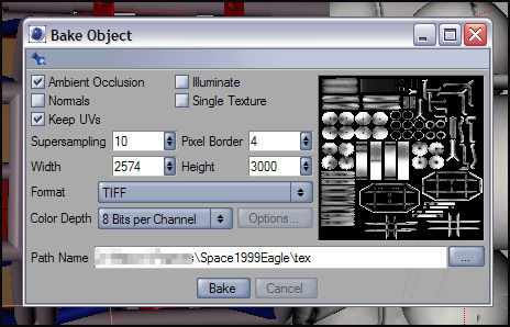
Once I was happy with the UV mapping, Ambient Occlusion was baked using the settings shown. This AO is used as a mask for a 'dirt' in my paint software. Much greater control using AO this way.


Becco_UK ( ) posted Sun, 05 April 2009 at 3:30 PM · edited Sun, 05 April 2009 at 3:32 PM

file_428034.jpg

The engine assemby in place. Marking and additional weathering to be done when all the other Eagle components are UV mapped and painted. The engine 'bells' still have some work to do, including adding a Saturn V kit part inside each 'bell'.


Mandrake7062 ( ) posted Mon, 06 April 2009 at 6:48 AM

Very neat stuff going here Becco. What the story on the weld? A plugin. Looks like it would be poly hungry.


contrafibbularities ( ) posted Mon, 06 April 2009 at 11:56 AM

Yes, very neat indeed!

I'm sure you'd have done the job just as well without my tutorial. You've got some serious skills, I admire your work a lot.

Cheers
contrafibbularities


Becco_UK ( ) posted Fri, 10 April 2009 at 3:48 AM · edited Fri, 10 April 2009 at 3:49 AM

file_428294.jpg

**contrafibbularities**: Thank you.

The side pods start to get built with a simple shape (a modified cube). Seing this reminds me of 3d graphics in the 1980's - few polygons and few colours!


Becco_UK ( ) posted Fri, 10 April 2009 at 3:53 AM

file_428295.jpg

The side pods have panelling and model kit detailing. One kit part from the 1/24 Scale Gemini kit has a couple of angles that look better if reproduced as accurate as possible. A few rough photo's help with this.


Becco_UK ( ) posted Fri, 10 April 2009 at 3:54 AM

file_428296.jpg

Side pod with the panelling and model kit parts added.


Becco_UK ( ) posted Fri, 10 April 2009 at 3:55 AM

file_428297.jpg

From the rear.


Becco_UK ( ) posted Fri, 10 April 2009 at 4:00 AM

file_428298.jpg

A render of all the bits made so far. The mirror tool is fine for some things but some model kit parts look wrong if they are mirrored so they are best copied and posisitioned seperately. The Saturn V kit parts gets modelled and added inside the engine bells.


Becco_UK ( ) posted Fri, 10 April 2009 at 6:47 AM · edited Fri, 10 April 2009 at 6:52 AM

file_428302.jpg

A preview render of how the side pods simply slide into the cage structure.


Becco_UK ( ) posted Fri, 10 April 2009 at 6:51 AM

file_428303.jpg

With the rear side pods added.


strata ( ) posted Fri, 10 April 2009 at 11:25 AM

Looks excellent so far! :) Strata 

“The scientists of today think deeply instead of clearly. One must be sane to think clearly, but one can think deeply and be quite insane.” Nikola Tesla


contrafibbularities ( ) posted Fri, 10 April 2009 at 2:39 PM

I second that! 😄 It's also one of the most informative WIP threads I've seen. Thanks for all those detailed screenshots, and the infos you're posting. It's almost like a tutorial, which is really great!

Cheers
contrafibbularities


Becco_UK ( ) posted Mon, 13 April 2009 at 9:48 AM

file_428529.jpg

**strata** & **contrafibbularities**: Thank you.

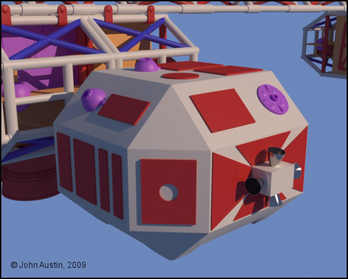
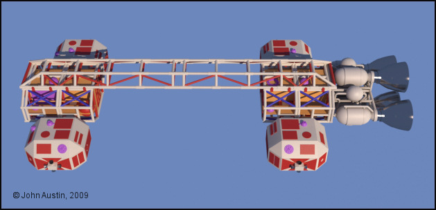
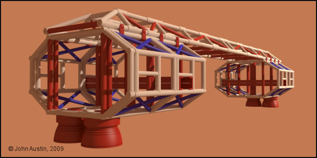
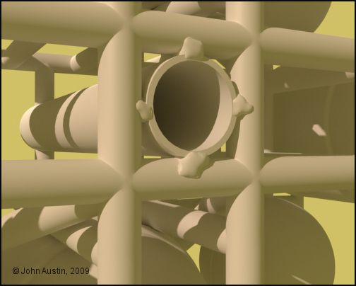
Still with the side pods, they are now UV mapped and each one has their own texture map. Ambient occlusion has been baked on them to use as a mask over a light brown 'spacedust' colour. Also, I've spent time reducing the polygon count of the 'cages' by selecting and 'melting' loops. Doing this has lowered render time polygons by almost 12,000 so that was time well spent.


Becco_UK ( ) posted Mon, 13 April 2009 at 9:50 AM · edited Mon, 13 April 2009 at 9:52 AM

file_428530.jpg

All the side pods in place - it would have been nice to have 'mirrored' those but that was not possible due to panelling variations. Markings and weathering to be added another time.


Becco_UK ( ) posted Tue, 14 April 2009 at 4:59 AM · edited Tue, 14 April 2009 at 5:00 AM

file_428587.jpg

Slowly starting to take shape. All metal parts include platinum data - although not strictly accurate I think the effect at render time is more in keeping with the model so far. Next stop - making the landing gear.


Becco_UK ( ) posted Tue, 14 April 2009 at 10:26 AM · edited Tue, 14 April 2009 at 10:35 AM

file_428596.jpg

One of the four landing gear assemblies gets underway on a base of raspberry jelly:-) - I'm modelling this structure in the flight position and then will try and sort out modement of the 'leg' and attached moveable parts.


Mandrake7062 ( ) posted Tue, 14 April 2009 at 10:31 AM

hmmm very tasty, very nice. Wish I had more time to model!!


Becco_UK ( ) posted Tue, 14 April 2009 at 10:38 AM

Mandrake7062: Thank you. I haven't seen much happening with your Eagle lately - is it finding the time or are you stuck with something?


Privacy Notice

This site uses cookies to deliver the best experience. Our own cookies make user accounts and other features possible. Third-party cookies are used to display relevant ads and to analyze how Renderosity is used. By using our site, you acknowledge that you have read and understood our Terms of Service, including our Cookie Policy and our Privacy Policy.
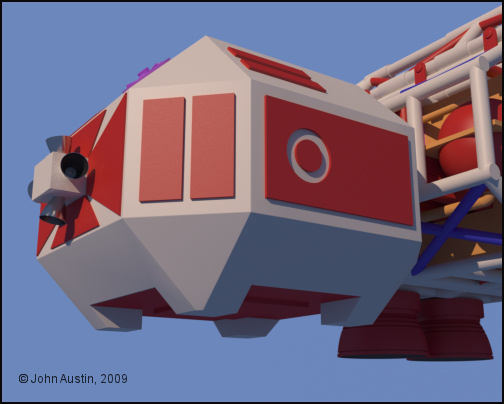
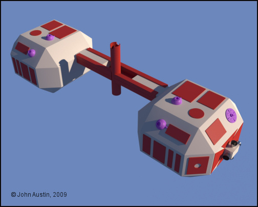
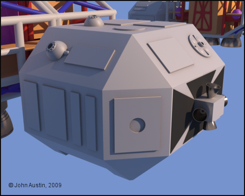
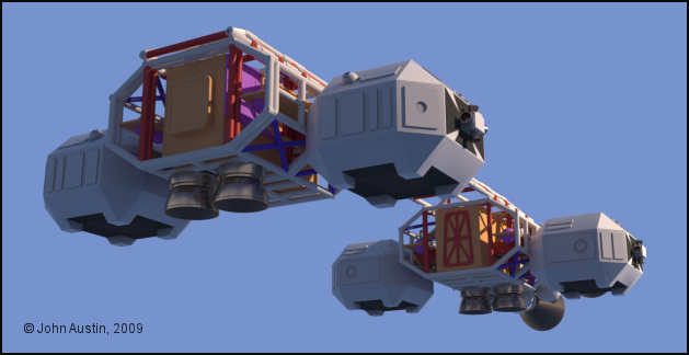
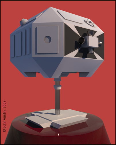