Renderosity Forums / Rhino 3D
Welcome to the Rhino 3D Forum
Forum Moderators: UVDan
Rhino 3D F.A.Q (Last Updated: 2024 Aug 27 11:07 am)
OFF SITE TUTORIALS
FORUM CHALLENGE RULES
NEWBIES GUIDE TO POSTING PICTURES
OFF SITE RESOURCES
RENDEROSITY HAS A ZERO TOLERANCE FOR ILLEGAL SOFTWARE USE OR REQUESTS TO OBTAIN ILLEGAL SOFTWARE
Checkout the Renderosity MarketPlace - Your source for digital art content!

Subject: how to create a solid from surface?

But now I have another problem:
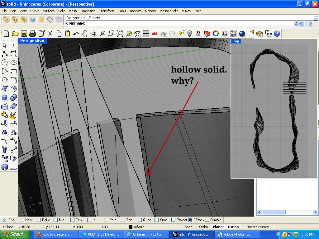
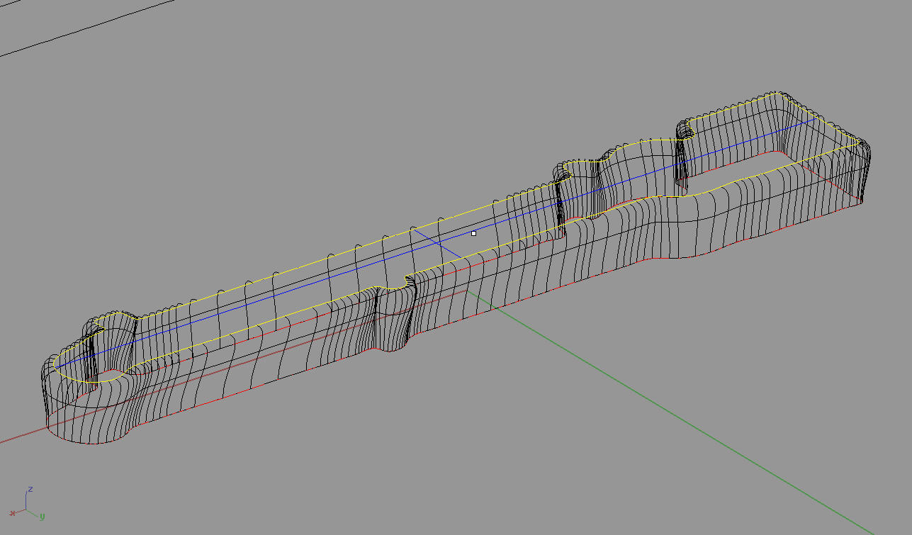
I want to cut this solid that I got into smal pieces with a distance between each other (take a look at the picture)
But the problem is that, when I do this, I realize that my solid is hollow. And because it is a hollow All this small cut pieces that I got, do not have a lateral sides (surfaces). This means that I need to create this lateral surfaces on each of those small pieces separately.
Well is there any other way I can create a solid which is not hollow, but a inner-filled?
Here is my .3dm file with the cutted pieces.
http://www.gamefront.com/files/20378555/solid2.3dm

The surfaces that you want to cap can be selected by using the bounding box selection method, and let Rhino figure out the rest. Ether a "window rectangle" or a "crossing rectangle" should do the trick for the mass selection.
I must not fear.
Fear is the mind killer.
Fear is the little death that brings total
obliteration.
I will face my fear.
I will permit it to pass over me and through me.
And when it has gone past, I will turn the inner eye to see its
path.
When the fear has gone there will be nothing.
Only I will remain.
Frank Herbert, author of Dune
I'd say so, Rhino will tell you if it has any issues. For this to work you must use planar surfaces for the cutting.
I must not fear.
Fear is the mind killer.
Fear is the little death that brings total
obliteration.
I will face my fear.
I will permit it to pass over me and through me.
And when it has gone past, I will turn the inner eye to see its
path.
When the fear has gone there will be nothing.
Only I will remain.
Frank Herbert, author of Dune
me too. And it worked fine also, thank you.
Now I am curious:
what if I would have curved surfaces for cutting this main curved solid. So instead of all this vertical planar surfaces I used for cutting, what if I would have a curved ones.
Then the "Cap Planar Holes" command would not work?
In that case I would have to use the "_EdgeSrf" (Surface from 2,3 or 4 edge curves) ?

In V4, there is a command called "_CreateSolid" that automates what Dan just said. I'd give that one a try.
I must not fear.
Fear is the mind killer.
Fear is the little death that brings total
obliteration.
I will face my fear.
I will permit it to pass over me and through me.
And when it has gone past, I will turn the inner eye to see its
path.
When the fear has gone there will be nothing.
Only I will remain.
Frank Herbert, author of Dune
thank you for the advices once again.
@UVDan: I tried you method and it works on my Rhino4 SR8
@EHNisja: I believe you that this works perfectly, but maybe on some other SR?
This is what I get when I type "_CreateSolid" command:
Quote -
Command: _Paste
Command: _CreateSolid
Select intersecting surfaces and polysurfaces to automatically trim and join into a closed polysurface:
Select intersecting surfaces and polysurfaces to automatically trim and join into a closed polysurface:
Select intersecting surfaces and polysurfaces to automatically trim and join into a closed polysurface. Press Enter when done:
Select intersecting surfaces and polysurfaces to automatically trim and join into a closed polysurface. Press Enter when done:
Solid creation in progress... Press Esc to cancel
Unable to create solid.
Hello George, I get that alot as well! I'm on sr8 also. Like I said, "I'd give it a try." It might not like that some of the surfaces are trimmed to the edge that is needed to make the closed polysurface. You sometimes can get lucky with the soilds tools but there's always the robust surfacing tools to fall back on.
I must not fear.
Fear is the mind killer.
Fear is the little death that brings total
obliteration.
I will face my fear.
I will permit it to pass over me and through me.
And when it has gone past, I will turn the inner eye to see its
path.
When the fear has gone there will be nothing.
Only I will remain.
Frank Herbert, author of Dune
Can I ask for one more question?
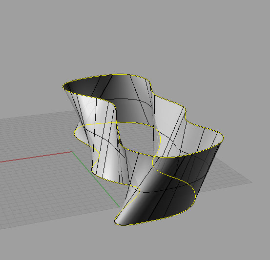
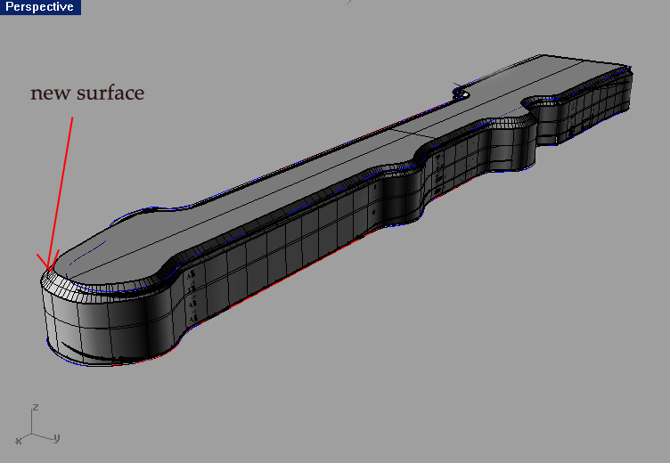
How can I make surface, similar to the one that I already had, but with the curved top.
for example before I had this (take a look at the image).
Here is a more closer example of what I want to do (take a look at the picture).
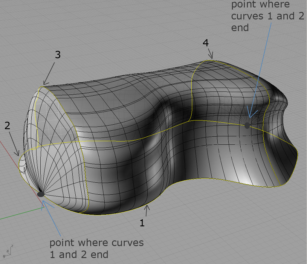
But I am definitively doing something wrong. Ok here is what I did with the Sweep To Rail 2 command.
I created the two "ends" of the surface:
First I used the curves 1 and 2 as the the first and the second rails, and then used the curve 3 as a crossection curve.
| did the same thing with curves 1,2 and 4: curves 1 and 2 as the the first and the second rails, and then used the curve 4 as a crossection curve.
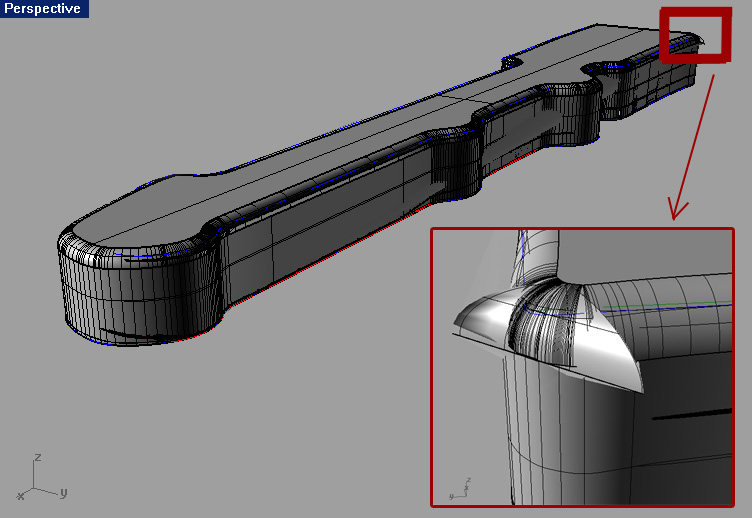
Then I created the "middle" part:
used curves 1 and 2 as the the first and the second rails, and then used both curves 3 and 4 as a crossection curve. And I got the middle part.
Bu the problem is that the transitions between the two "ends" and the "middle" part are two sharp. How can I fix this?
Here is the .3dm file:
http://www.gamefront.com/files/20386569/solid.3dm
But I am definitively doing something wrong. Ok here is what I did with the Sweep To Rail 2 command.
I created the two "ends" of the surface:
First I used the curves 1 and 2 as the the first and the second rails, and then used the curve 3 as a crossection curve.
| did the same thing with curves 1,2 and 4: curves 1 and 2 as the the first and the second rails, and then used the curve 4 as a crossection curve.
Then I created the "middle" part:
used curves 1 and 2 as the the first and the second rails, and then used both curves 3 and 4 as a crossection curve. And I got the middle part.
Bu the problem is that the transitions between the two "ends" and the "middle" part are two sharp. How can I fix this?
Here is the .3dm file:
http://www.gamefront.com/files/20386569/solid.3dm

Rhino has limitations when it comes to these types of surfaces. Amorphous, closed, continuosly curving surfaces are tough to create using a NURBS program. Sweep 2 Rails works best if the rails never meet. The closer the rails become, the more deformed the surface becomes. There are many methods you can use that can approximate the shape you are looking for. The trick is keeping your model clean, with as few surfaces, booleans, and fillets as possible. Remember, Rhino is a precision tool: it works best if you know the exact dimensions, angles, and shapes you desire to model. If you are looking for a "free-form" modeler that will allow you to be more flexible with your objects, I would suggest you look to polygonal modeling tools such as Blender.
I will try a few solutions and post images if I come up with something suitable. In the meantime, you may want to play around with Rail Revolve. I would also suggest using control points to "sculpt" a surface that is acceptable.
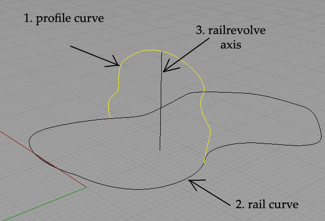
Hello George, You will need to split curve #1 with curve #3 and use only one of the halves to get the correct results from the rail revolve command.
I must not fear.
Fear is the mind killer.
Fear is the little death that brings total
obliteration.
I will face my fear.
I will permit it to pass over me and through me.
And when it has gone past, I will turn the inner eye to see its
path.
When the fear has gone there will be nothing.
Only I will remain.
Frank Herbert, author of Dune
thank you for the tip once again EHNisja.
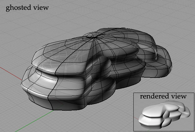
I did it like you told me, and now I am more closer to what I want to do (look at the image).
But I want my surface to change along the rail. Not to be the same, like it is in the case of using the "RailRevolve" command.
That`s why I tried to use the "_PointsOn" (control points) command.
But it says:
"Cannot turn on points for polysurfaces."
So what should I do?
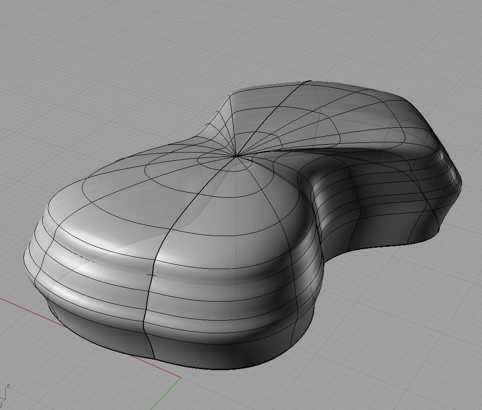
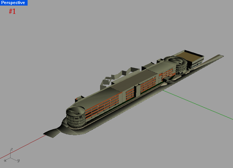
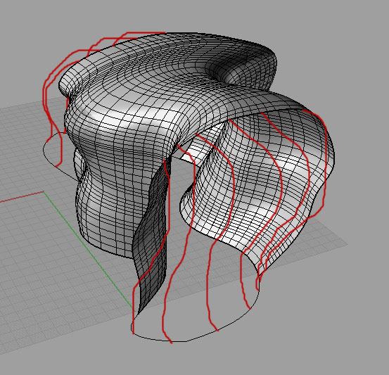
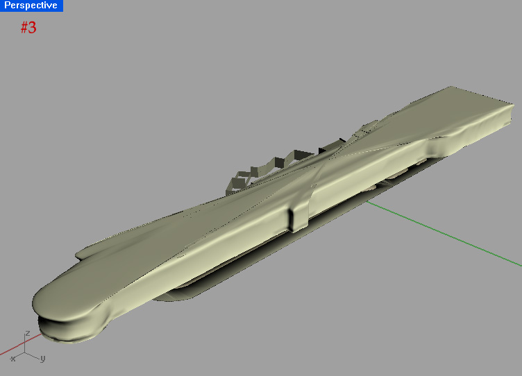
I am trying to create a free shaped facade all over my parking garage.
But it seems that RailRevolve can not be implemented in this case, maybe because of the longitudinal characteristic of my object. The biggest problem lies in the top part of the surface which is very deformated (image #3).
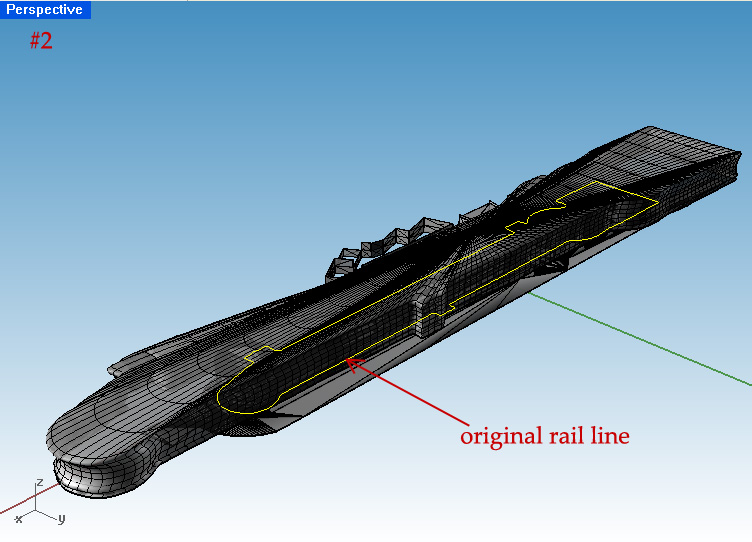
And also my created surface is bigger than it should be. A lot bigger. Take a look at the image #2.
what should I do, and how can I create this surface?
Here is the .3dm file:
http://www.gamefront.com/files/20403317/Untitled.3dm
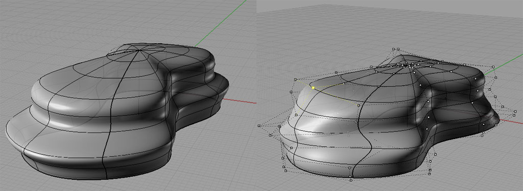
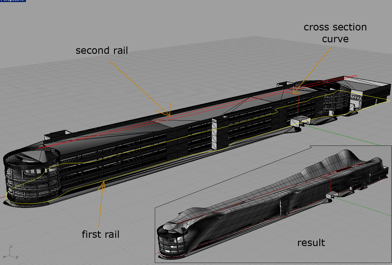
I would try a sweep2 surface, the inner rail could be a long oval and outer rail is your original rail curve. In the sweep2 command you can "add slashes" that will allow Rhino to control the surface better. Your profile curves will be the general shape of the surface needed.
I must not fear.
Fear is the mind killer.
Fear is the little death that brings total
obliteration.
I will face my fear.
I will permit it to pass over me and through me.
And when it has gone past, I will turn the inner eye to see its
path.
When the fear has gone there will be nothing.
Only I will remain.
Frank Herbert, author of Dune
You will need to make the "inner rail". It will be at the elevation that you want the top of your surface to finish at and in the middle of your original rail, it will be oval- like in shape. The sweep2 command needs to have 2 separate curves to guide Rhino in the making of the surface. In this case they will both be closed cuvres. The small area that is left in the middle can be closed using the patch command.
I must not fear.
Fear is the mind killer.
Fear is the little death that brings total
obliteration.
I will face my fear.
I will permit it to pass over me and through me.
And when it has gone past, I will turn the inner eye to see its
path.
When the fear has gone there will be nothing.
Only I will remain.
Frank Herbert, author of Dune
Experiment with the different surface tools to see the style of surface that they make and use the parts that you like to form the surface that you need. If this is going to be a "real" structure, you need to keep in mind construction costs. I would hate to figure out how much this one would cost to make!
I must not fear.
Fear is the mind killer.
Fear is the little death that brings total
obliteration.
I will face my fear.
I will permit it to pass over me and through me.
And when it has gone past, I will turn the inner eye to see its
path.
When the fear has gone there will be nothing.
Only I will remain.
Frank Herbert, author of Dune
The "blend surface" command needs two surfaces to work with. I used 5 units just to get enough to work with. I deleted it as soon as I was done using it. Rhino uses the UVs of BOTH sets of surfaces to make the blend. If you extruded the outer surface with a taper, you would get a whole different outcome! You might want to try it, I think that it could have a neat effect.
I must not fear.
Fear is the mind killer.
Fear is the little death that brings total
obliteration.
I will face my fear.
I will permit it to pass over me and through me.
And when it has gone past, I will turn the inner eye to see its
path.
When the fear has gone there will be nothing.
Only I will remain.
Frank Herbert, author of Dune

different way: planar surface out of the lower curve --> extrude the surface and bevel the edges...
No, you're right chamfer edges is not the right one.
The command in my german version "kante verrunden" means "bevel edge" translated into english and in Maya, the other 3d program I use, it's called that way...I got a bit confused...
So the correct command for you would be "_FilletEdge" (Select the top edge) This gives you a nice round edge (you can change the radius for a bigger/smaller bevel). And as a second advantage your extruded walls will be perfectly straight.
I'm a bit curious...do you make the model for yourself or for a client?
By the way, I am a student. I am making the model for my faculty project.
P.S.
I love your "Fragile" movie! Fantastic work. I did not know that Rhino has that powerfull video making abilities.
Thanks! I have to dissapoint you though...I did just some of the modeling in Rhino, the animation/rigging part was created with autodesk maya 2012.
I have my last day of school tomorrow :biggrin: ...after the summer break I'll be studying architecture too.
Your mesh issue could be connected to your display settings. Type "_DocumentPropertiesPage" hit Enter & Enter again. Now in the Document property window (on the left side) under Documentproperties-->Polygonnet select "smooth and slower" instead of the default "faster" option.
thank you for the advice.
but I did not have a chance to test it. As I did not saved the change of my previous work. So I tried to do the same procedure again: create the planar surface from the bottom curve, extrude this planar surface and then Filletedge of its upper edge. Now everything worked without problems.
But I will keep in mind your last tip about the "smooth and slower" issue.
I wish you all the best with your studies. Architecture is a great profession.
You are 18 years old? Great Rhino knowledge, I must admit.
Privacy Notice
This site uses cookies to deliver the best experience. Our own cookies make user accounts and other features possible. Third-party cookies are used to display relevant ads and to analyze how Renderosity is used. By using our site, you acknowledge that you have read and understood our Terms of Service, including our Cookie Policy and our Privacy Policy.
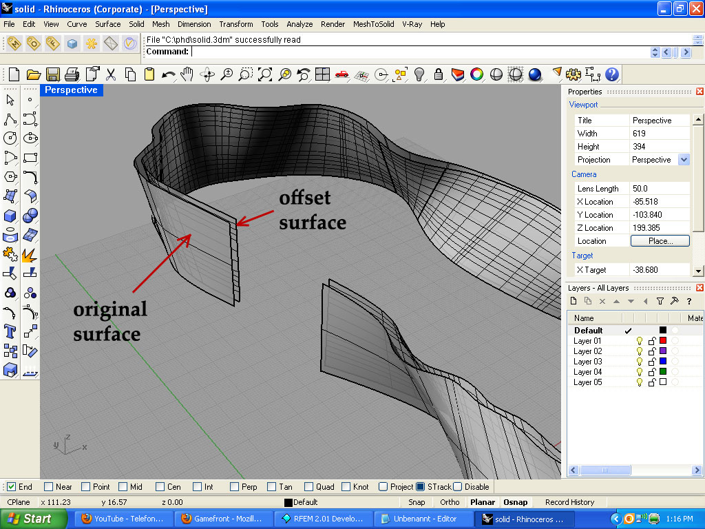
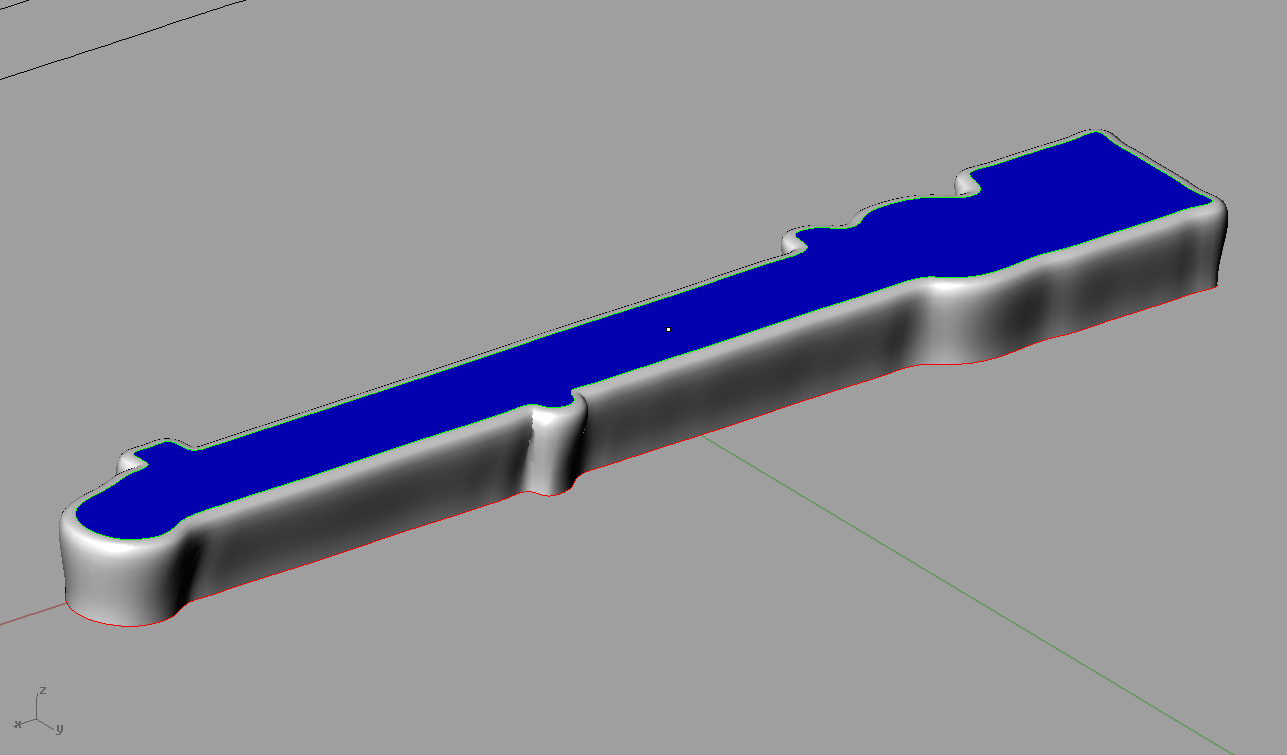
I want to create a solid from my curved surface.Take a look at the picture above: I have an original curved surface, and then I made an offsetted one to the inner direction. This offesetted surface should be bounday untill which I want to create a solid.
So how can I do this?
Here is my .3dm file:
http://www.gamefront.com/files/20378138/solid.3dm
Thank you.