Renderosity Forums / Carrara
Welcome to the Carrara Forum
Forum Coordinators: Kalypso, Anim8dtoon
Carrara F.A.Q (Last Updated: 2026 Jun 30 12:55 pm)
Visit the Carrara Gallery here.

Subject: Help with airplane model tutorial

Just go to the texture room and add a texture to the color channel. This should place the image on the plane stretched to fit. If you only see half of it, set it to tile twice and that should tile it across the front and back. An infinite plane will HEAVILY distort your image when it's displayed, because C will try to stretch the image over an infinite plane. UGLY! A plane is the size you make it and will not overly distort your tracing image. If you insert a plane with the tool, instead of using the menu, and then click in the side view, it will place it perpendicular to your view. I.E. on it's side vertically. Or you can also, like Kix said, rotate it numerically with the properties tray. Hope this helps!
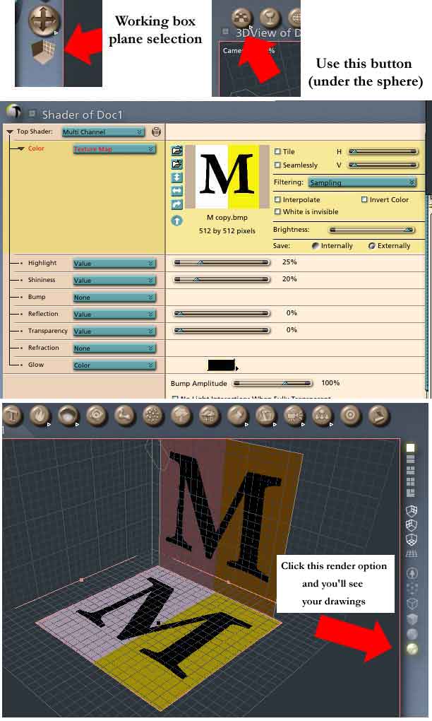
Well that worked great. The problem is that once I insert the planes and texture them I can only see them in the Assembly Room. The tutorial tells you to hand draw the parts of the airplane in the Spline Modeler, extrude, and then switch to the Assembly Room, line them up against the textured blue prints and adjust as needed. Isn't there a better way than this? Can I put the blue prints into the Spline Modeler and trace them? This sure would speed things up a bit. Thanks...
What you need in the Spline Modeler is cross-sections. As the tutorial says, the best way of getting these is to do them in Illustrator and import them - not very helpful if you haven't got Illustrator (but they are on the CD). Drawing them in the SM is not easy as, as you say, there's no way of tracing. It is possible to see what you are doing in the Preview window though, and you can drag this to enlarge it, move stuff around etc., all from within the SM (But to see the plans make sure the Textured render button is clicked like in the Assembly Room).
"As the tutorial says, the best way of getting these is to do them in Illustrator and import them - not very helpful if you haven't got Illustrator (but they are on the CD)." The images on my CD are TIFF format and not AI format. I guess I could import them into AI and then save them. If I read the manual correctly (and correct me if I am worng) you can import images into the Spline Modeler but only in AI format?
I suppose you are talking about the wing cross-sections. I think you'll find the fuselage cross-sections are there, in their own folder, in ai format. I should have thought the the wing cross-sections would be easy enough to draw without a reference other than the illustration on p100. You can import only ai format files into the Spline Modeler. This is so that you can import cross-sections 'ready-made' (rather than using them as a background image).
Privacy Notice
This site uses cookies to deliver the best experience. Our own cookies make user accounts and other features possible. Third-party cookies are used to display relevant ads and to analyze how Renderosity is used. By using our site, you acknowledge that you have read and understood our Terms of Service, including our Cookie Policy and our Privacy Policy.
I am in the process of going through the Carrara Studio 3 Handbook by Mike DeLaFlor and on the first tutorial on building the airplane it leaves out some very important information and just assumes you know how. The part I need help out with is this, it tells you to place two planes perpendicular to each other in the assembly room and attach the tif images of the airplane to each of them.
I was able to play around with the planes and get them somewhat at 90 degree angles to each other but it seems like there should be a easier way. Also each time I inserted the plane it was loaded on the floor. Is ther a way to load it against the sides? And how do I attach the tif images to the planes? And is there any difference between inserting a plane and a infinite plane?
If I can get this information I can proceed on...