Renderosity Forums / 3D Modeling
Welcome to the 3D Modeling Forum
Forum Moderators: Lobo3433 Forum Coordinators: Digitell
3D Modeling F.A.Q (Last Updated: 2026 Mar 17 3:46 pm)
Freeware 3D Modeling Software Links:
Blender | Trimble Sketchup | Wings 3D | Anim8or | Metasequoia | Clara IO (Browser-based 3d modeler)
Check out the MarketPlace Wishing Well, as a content creator's resource for your next project.
"What 3D Program Should I buy?" Not one person here can really tell you what's best for you, as everyone has their own taste in workflow. Try the demo or learning edition of the program you're interested in, this is the only way to find out which programs you like.
Checkout the Renderosity MarketPlace - Your source for digital art content!

Subject: Quick Tutorial: Modeling a simple button, with all quads, no booleans.

______________________________________
My Store
My Free Models
My Video Tutorials
My CG Animations
Instagram: @luxxeon3d
Facebook: https://www.facebook.com/luxxeon

______________________________________
My Store
My Free Models
My Video Tutorials
My CG Animations
Instagram: @luxxeon3d
Facebook: https://www.facebook.com/luxxeon

______________________________________
My Store
My Free Models
My Video Tutorials
My CG Animations
Instagram: @luxxeon3d
Facebook: https://www.facebook.com/luxxeon

______________________________________
My Store
My Free Models
My Video Tutorials
My CG Animations
Instagram: @luxxeon3d
Facebook: https://www.facebook.com/luxxeon

______________________________________
My Store
My Free Models
My Video Tutorials
My CG Animations
Instagram: @luxxeon3d
Facebook: https://www.facebook.com/luxxeon
______________________________________
My Store
My Free Models
My Video Tutorials
My CG Animations
Instagram: @luxxeon3d
Facebook: https://www.facebook.com/luxxeon
______________________________________
My Store
My Free Models
My Video Tutorials
My CG Animations
Instagram: @luxxeon3d
Facebook: https://www.facebook.com/luxxeon
______________________________________
My Store
My Free Models
My Video Tutorials
My CG Animations
Instagram: @luxxeon3d
Facebook: https://www.facebook.com/luxxeon
______________________________________
My Store
My Free Models
My Video Tutorials
My CG Animations
Instagram: @luxxeon3d
Facebook: https://www.facebook.com/luxxeon
______________________________________
My Store
My Free Models
My Video Tutorials
My CG Animations
Instagram: @luxxeon3d
Facebook: https://www.facebook.com/luxxeon
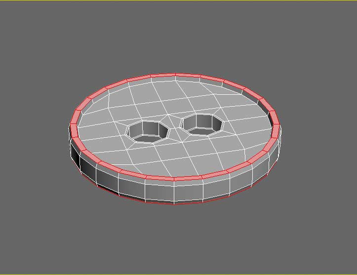
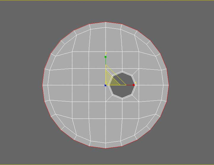
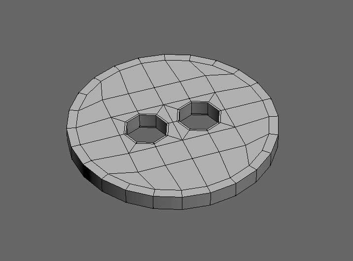
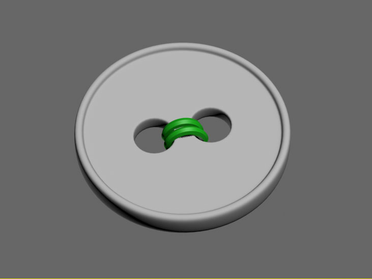
Select the outter ring of quads at the top and bottom of the model, and extrude/bevel them slightly, as shown in the example picture.
______________________________________
My Store
My Free Models
My Video Tutorials
My CG Animations
Instagram: @luxxeon3d
Facebook: https://www.facebook.com/luxxeon

______________________________________
My Store
My Free Models
My Video Tutorials
My CG Animations
Instagram: @luxxeon3d
Facebook: https://www.facebook.com/luxxeon
______________________________________
My Store
My Free Models
My Video Tutorials
My CG Animations
Instagram: @luxxeon3d
Facebook: https://www.facebook.com/luxxeon
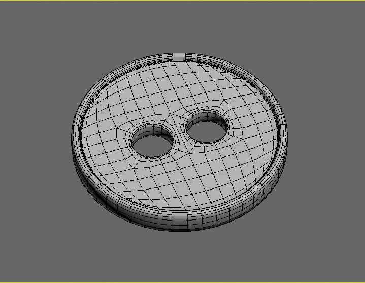
Hope you found this useful. If you're a beginner at modeling, this might be a good way to get to know your edge loop tools, and how to punch holes in objects without using sloppy boolean functions. Good luck! ;)
______________________________________
My Store
My Free Models
My Video Tutorials
My CG Animations
Instagram: @luxxeon3d
Facebook: https://www.facebook.com/luxxeon
PS: If you are a 3dsmax user, and using a version of Max that doesn't allow for Circularizing edge loops in your Loop Tools panel, or if the command isn't producing adequate results, then download this free Maxscript called Loop Regularizer. It works in 3dsmax ver 9 and above, and allows you to circularize edge, border, and face loops with a single click, and produces accurate, predictable results every time.
In Wings3D, Circularise is a command in Edge Mode, and use constraint key to snap.
______________________________________
My Store
My Free Models
My Video Tutorials
My CG Animations
Instagram: @luxxeon3d
Facebook: https://www.facebook.com/luxxeon

Good tutorial with some good tips. I don't mean to throw a wrench in it, Lux, but you really should mention that in order to complete the first step of this tut like you have done here, in ANY version of 3dsmax, you will NEED to download and use that free maxscript. The regular "circle" tool in the 3dsmax loop tools panel will only work on square edge loops with NO interior segments. So to create a quad circle from a square plane without that script, you would need to create the square plane, then delete or remove all the interior edges first, WITHOUT removing the vertices (just hit remove without pressing CTL), then apply the "circle" command from loop tools panel, then add the segments or edges back again in order to get the same results. So it would be a few more steps. On the second part, making the hole, you would need to first delete those faces, then select the edges of the resulting hole only, and apply the "circle" command again from loop tools, because it won't work directly on face selections, only edge loops. You would need that script installed to circularize the face selections, like in your tutorial.
Granted, the maxscript is free, and very useful as we can plainly see, but the first part of your tut where you make the plane into a quad circle isn't possible the way you have said in any version of 3dsmax, not just early versions, UNLESS you have that maxscript installed. Just FYI and headsup to novice Max users out there, who might be perplexed as to why it's not working out for them.
Attached Link: http://www.scriptspot.com/3ds-max/scripts/loop-regularizer
Wow. Seems you are correct about that, Sinner. I have that script mapped to a hotkey, and I have been using it for so long, I simply forgot that it's not the standard Circle loop tool command. Well, if you are a 3dsmax user, and wish to follow this tutorial, then definitely download the [**Loop Regularizer**](http://www.scriptspot.com/3ds-max/scripts/loop-regularizer) script at the link attached. Install it, and map it to a hotkey as I've done. Trust me, you'll find it will become part of your standard workflow very quickly. Sorry for that.What about users of other applications? Is anyone finding a problem creating a quad circle? If this is a problem in other software applications, then my apologies. Again, the alternative way to get to the starting point of this tutorial (a quadrangular circle) would be to create a quad cylinder with 24 sides, and detach the cap faces, or flatten a quad sphere with sufficient segments.
______________________________________
My Store
My Free Models
My Video Tutorials
My CG Animations
Instagram: @luxxeon3d
Facebook: https://www.facebook.com/luxxeon

Or
Delete the 4 faces where the hole is and add an 8 sided cylinder, delete the end cap, and bridge. Then just delete the bits you don't need before the thicness extrude. Many ways to skin the proverbial cat.
http://www.renderosity.com/mod/forumpro/showthread.php?thread_id=2868853
Anyone tried this?
Quote - Or
Delete the 4 faces where the hole is and add an 8 sided cylinder, delete the end cap, and bridge. Then just delete the bits you don't need before the thicness extrude. Many ways to skin the proverbial cat.
http://www.renderosity.com/mod/forumpro/showthread.php?thread_id=2868853
Anyone tried this?
Yes, I've also created a classic soccer ball in 3dsmax, and the process is much faster than the Cinema4D tutorial; mostly because in Max we are able to begin with a virtual soccer ball primitive object, then just tessellate to create quad topology between Ngons, and bevel the original edges to create the seams.
I was going to offer the model for free, but figured it was far too easy to make, with too many tutorials out there for it, and perhaps no one would even be interested to download one. I may reconsider that, however, after seeing how long the process is in the Cinema4D tutorial you linked to (20 minutes).
______________________________________
My Store
My Free Models
My Video Tutorials
My CG Animations
Instagram: @luxxeon3d
Facebook: https://www.facebook.com/luxxeon
Quote - OH great a soccer ball primitive! - where's the fun in that
Good tut, though as you say a bit lengthy.
I haven't tried it yet, I was just amazed that, from the icosphere, it gave the right shaped divisions
Haha. Well, it's actually an hedra primitive, which is a parametric primitive shape that, through some parameter adjustments, can create several families of polyhedra very quickly. Here's a Youtube tutorial on how to create the same kind of soccerball in 3dsmax, in about 6 minutes:
http://www.youtube.com/watch?v=3t3twBfUNOY
http://www.youtube.com/watch?v=OyedOFFEu3k - This guy does it in about 9 minutes without assigning material zones, but he gets 100 percent quad topology. There's a few NGons I noticed in the previous example, which are fine in some apps, but won't translate to every app. I did my soccerball with material zones in about 10 minutes; all quads.
Hedra Primitive in 3dsmax - Explaination of the primitive object.
I'd be interested in seeing how you approach this kind of button that I've done here in your modeling app, airflames. It may be useful to others, and help get past the first part of the tutorial, as it seems some may have issues achieving a quad circle in other applications if they can't circularize the plane, or have access to a quadrangulated cylinder cap.
______________________________________
My Store
My Free Models
My Video Tutorials
My CG Animations
Instagram: @luxxeon3d
Facebook: https://www.facebook.com/luxxeon
Lux, I wouldn't worry about if people could get the quad circle to start anyway, because anyone should be able to figure out how to do this in their modeling application as a basic exercise, and good practice.
If you don't have a cylinder which has end caps made from quad segements that you could use, then the workaround to achieving a decent 100% quad circle is as follows:
Use ANY cylinder primitive as a TEMPLATE for the circle shape. Even if it has ngon or triangulated end caps, it doesn't matter, because that's not going to be used for creating the geometry. In the TOP viewport, create the plane as Luxxeon has illustrated in the beginning of this tutorial OVER the top end of the cylinder, so that the cylinder is situated directly beneath the plane in the center. Lock the cylinder object's position so you can't accidentally select it. Switch to wireframe mode, or transparency mode, so that you can visibly see both the edges of the plane and the underlying edges of the cylinder, then in VERTEX mode, start manually rearranging the vertex points of the plane's border edge to match the edge of the cylinder, which in top view should look like a circle shape. Get the vertices as close to the quad circle Lux has shown in this tutorial as possible, because it's nearly a perfect quad grid, which will give good results for subD smoothing and UV mapping, and then you can continue with the rest of the tut. Should be simple and straightforward to do in just about any app.
Well, as SinnerSaint describes just drag and snap to a circular template.
I just built from 2 cylinders - 18 on the outside and 6 on the hole. Filled in some geometry in between, and so on. 3k quads. I did have a spherify plugin but I've dismissed it at some point.
MOst folks seem to be using Blender so I'm pretty sure that that has circularise. I think its ctrl/alt/+/7/MMB. Only joking folks!
No chance with the football though - I'd need some sort of primitive.
As far as I'm aware, Blunder, I mean BlEnder (sorry I just had to do it), would require a loop tools addon to convert a border edge selection to a circle, but you need to grow 20 fingers to activate it from a hotkey. Just kidding... I can already see the blender fans loading their 3D printed guns to shoot me. I like Blender, it's powerful, but it's modeling tools just aren't the most efficient i've ever used.

This is how I'd go about it in LightWave. I did think starting with a square was a bit counter intuitive, but otherwise, pretty much the same idea, similar tools and techniques used.


Ignore the gradation in that last last images, I compressed the images pretty hard so they wouldn't be too large in file size.
Step 0 - Just a rough mock up of the size I wanted things to be. Furniture tends to use pretty heavy thread, so I wanted larger holes relative to the over all button size than what LuxXeon had.
Step 3-5 - Once I saw how many edges I needed to match what I got from the two holes, I made a 12 sided disc.
Step 7 - I patched the the disc and the two holes together, then with a bevel tool gave the edge the approximate shape I wanted.
Step 8 - Mirrord the top to the bottom so I'd have all the geo I need to work with.
Step 9-11 - Flattend the bottom cause I don't need the same shape, and removed some edges. Then patched the top to the bottom.
Step 12 - I ran a "smooth" operation on the highlighted ring, just to even out the geometry a bit on the top face. Note the more even distribution of the highlighted ring in step 12 compared to previously in step 4.
Step 13-14 - Selected the top half, and using a move tool with radial fall off, I added a convex curve to the top of the button to give it a bit more shape.
Step 15-16 - The button itself is 232 quads. Added the thread, and subpatched it.
Core i7 950@3.02GHz | 12GB Corsair Dominator Ram@1600mHz | 2GB Geforce GTX 660
Lightwave | Blender | Marmoset | GIMP | Krita
Warlock279, excellent work! I agree with the thicker threading for furniture, but I've seen some cheap upholstered stuff, where the buttons were merely ornamental, and very thin threading wrapped heavily through the holes was used. I like Luxxeon's idea of starting out with a plane IF you can circularize it, because of the extraordinarily clean and uniform topology it provides, but I agree, I would have probably started with something closer to your example.
Even though Luxxeon's method contains less manual input (only if you have 3dsmax with that maxscript), I think Warlock's method is much more universally sound, and should work in literally ANY polygon modeling software.
Glad you posted that. I'd like to see someone post a nurbs strategy for this object. Any Rhino users out there?

Good work on your Lightwave example, Warlock279. It definitely shows there's a lot of different ways to attack a model like this, and keep within the primary goal; which is to illustrate how to quckly create a polygonal object with holes, without without using booleans, and maintain a good clean quad topology. I actually like the edge flow of your button there, which is a little more rounded in the middle than mine. Theres so many variations of a button, it's nearly impossible to make one that doesn't actually exist somewhere.
______________________________________
My Store
My Free Models
My Video Tutorials
My CG Animations
Instagram: @luxxeon3d
Facebook: https://www.facebook.com/luxxeon
Quote - all well and good, but i am interested in the poly count here. lets bear in mind that this is a button and not really a hero object.
It's easy to optimize this, even if you wanted to add two levels of subD. I removed the backfaces of my button, because it was being used on top of another surface, and with a little cleanup of some useless edges after one iteration of subdivision, I was able to get the object down to 1300 quads. If I was using the object in a scene where it wouldn't be visible as clearly, or seen at a distance, I may forego subD altogether, and simply vertex smooth the object, and then I have an object with only 508 quads.
______________________________________
My Store
My Free Models
My Video Tutorials
My CG Animations
Instagram: @luxxeon3d
Facebook: https://www.facebook.com/luxxeon
Edit... a little more optimizing of edges on the version with SubD, and I got it down to 800 quads with 1 iteration of SubD, and 200 quads with simple vertex smoothing. I think that is quite acceptable for a button with a raised edge. If I didn't extrude the edge to make it thicker, and if I decided not to chamfer the edges I'd probably get it down to a minimal 100 quads, but it wouldn't look as good under scrutiny, in close-up renders using today's unbiased physical lighting engines. My concern about any object I model is how it holds up under physically accurate lighting conditions, because most of today's engines are VERY picky about how the object is constructed, and objects without much detail really look like crap when Path Traced. If there aren't sufficient amount of segments, then artifacts and faceting begin to become aparent. Also, if I were to take an object, not a button obviously, but other objects, to 3D print, then detail matters. You can't 3D print or fabricate a bump map or normal map. ;)
______________________________________
My Store
My Free Models
My Video Tutorials
My CG Animations
Instagram: @luxxeon3d
Facebook: https://www.facebook.com/luxxeon
Quote - Blender, add grid, select outer edges of grid, Transform To_Sphere=1. Blender has a tool/function to do everything in the OP's tut.
Thanks for posting! That's good info to know, and I'm relieved to know for sure that the particular operation is something that can be done easily in other apps as well. I didn't wanna post an application-specific tutorial in this forum.
______________________________________
My Store
My Free Models
My Video Tutorials
My CG Animations
Instagram: @luxxeon3d
Facebook: https://www.facebook.com/luxxeon

Here's my shot using my older version of Max. Same exact technique as Luxxeon's OP, except that I started with a 4x4 grid, instead of his recommended subdivision amount. I decided not to go fancy with any edge bevels or crap. NO subdivision smoothing as you can see. Kept the poly count as low as I could for a circular object. I think it looks good enough for most distant shots where you need a button. Poly count here is a mere 176 quads. If I deleted the useless polygons on the back side, which would never be seen if your button is sitting on another object, then I reduced the polycount to a measly 104 quads, which is good for any of today's game engines.
I like the technique. Got this knocked out in under 2 minutes, and I was screwing around in the meantime with some alternate tricks, but decided to just go simple.
Sinner, I think the holes in your button are spaced a little too far apart, as a result of starting with a lower res quad plane. It's rare you see buttons where the holes are that far apart relative to the overall surface area of the object. I suppose you could select those edges and move them closer together manually afterwards, but 6x6 is the minimum resolution I recommend for getting the correct topology to work with. There's a lot of room at the end of the procedure to optimize the subdivided mesh, as I pointed out earlier, and get it down to reasonable polycounts for any purpose, if so desired.
Not to mention, you could always simply bake the high resolution verison to normal maps or displacement maps for use on the lower resolution cage.
______________________________________
My Store
My Free Models
My Video Tutorials
My CG Animations
Instagram: @luxxeon3d
Facebook: https://www.facebook.com/luxxeon
Privacy Notice
This site uses cookies to deliver the best experience. Our own cookies make user accounts and other features possible. Third-party cookies are used to display relevant ads and to analyze how Renderosity is used. By using our site, you acknowledge that you have read and understood our Terms of Service, including our Cookie Policy and our Privacy Policy.
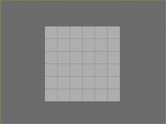
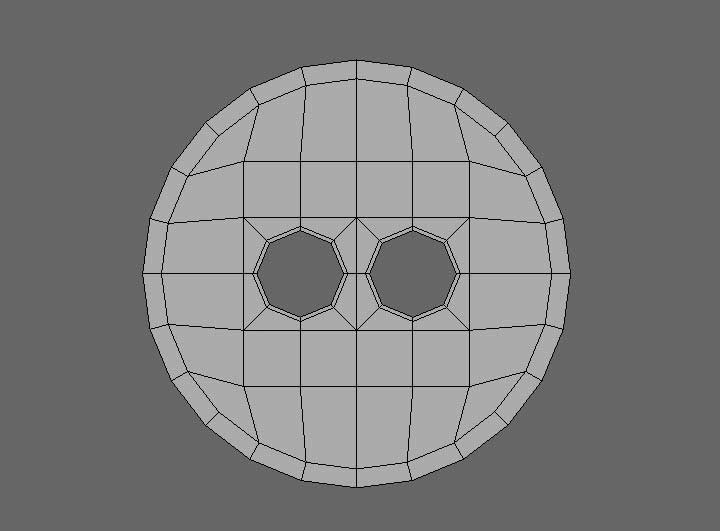
Hey, all. I was in the process of modeling an apholstered chair model, which required some simple sewing buttons to add detail to the surface, and it occured to me the many variety of techniques in which I've seen people model these objects. So, I thought I'd post this quick step-by-step tutorial showing ONE way to quickly model a simple, but effective, button object that is made of 100% quadrangular topology, without using Booleans, or any mesh cutting tools (except to delete faces).
This is just one way I like to go about it when I need to create a custom button really quick, and wish to maintain a quad-based mesh. I'll be using 3dsmax 2012 for this tutorial, but keep in mind the topology output generated by this technique is clean and efficient, using standard polygon modeling tools, and should translate to any capable modeling software. Again, there may be other ways to go about this, depending on the tools in your modeling application of choice; like starting with a cylindrical cap, using scripted plugins, etc. This method, unlike some of those alternatives, helps to avoid pole distortion, and maintains clean UV's, if you need to add textures. So here we go...
______________________________________
My Store
My Free Models
My Video Tutorials
My CG Animations
Instagram: @luxxeon3d
Facebook: https://www.facebook.com/luxxeon