
Renderosity Forums / Poser - OFFICIAL
Welcome to the Poser - OFFICIAL Forum
Forum Moderators: RedPhantom Forum Coordinators: Anim8dtoon
Poser - OFFICIAL F.A.Q (Last Updated: 2026 Nov 10 6:47 am)

Subject: maybe someone can fix this for me cause im tired and i dont think i did this rig

- 1
- 2

akura_
I'm not sure I understand what you are saying here. Do you mean that when you create the figure, the left arm is missing? Or are you loosing the arm at some other stage? Are you using the Robot-C-01.obj I sent you, or the update you just posted? If it's the update, try using the first version. What did you change in the update?
... To continue.
In the last step we set the joint parameters (JPs) for the ForeArms. In this step we will do the Shldrs. You should have saved a pz3 after the last step so open that up.
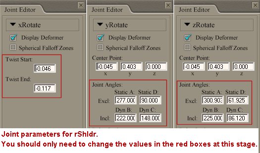
Select the rShldr (Right Shoulder) and open the joint Editor. Set the Joint parameters as in the image above. Memorize the figure, then do Symmetry > Right to Left. Memorize the figure again.
Save a pz3. Try out the bends of the shoulder to test how they work. The values that I am giving for the JPs are just my idea of what works reasonably well. You may be able to find values that work better, but I recommend that you stick with my values until we have finished rigging the figure, so that we are all singing from the same hymn sheet.
To be continued...
Quote - akura_
I'm not sure I understand what you are saying here. Do you mean that when you create the figure, the left arm is missing? Or are you loosing the arm at some other stage? Are you using the Robot-C-01.obj I sent you, or the update you just posted? If it's the update, try using the first version. What did you change in the update?
what happened is when i make the prop into a figure an using the group tool pressed spawn props. then closed set up and went to delete the prop. only right arm is missing. the other parts arnt.
hmmmm i think i see what happened. yes yes i got it working now =)
Quote - (click image for larger view)
... To continue.
In this step we will position the joint centers. The joint centre is the point around which the actor will rotate when a body part is bent. There is often no unique "correct" placement for the joint center, you just have to experiment and find what works best.
Les I noticed that you had an endpoint setting for the right forearm. I am unable to type anything into those fields to set them. Is it just me or am I missing something here. Everything else up to this point is good to go.BTW thank you very much for the tut. I really appreciate it. Moving on to the next step of adjusting the joint parameters.
Sorry lesbentley. I see farther down the thread that this problem is a non issue. Sorry for the interruption. Please carry on. I'll pay a little more attention in the future
Quote - alright =) for some reason there still conceder props thats ok right? the rigging is later?
Once you do the step of creating the figure in the Hierarchy Editor, every body part should be an actor in the figure. The figure will have been saved to the Figures palette, under the New Figures section. First start a new blank scene, then load the figure from the New Figures palette. If you now open the the drop-down menu at the top of the Document Window, and look at the props section, you should only see "GROUND" and "CenterOfMass". I probably forgot to say to open a new scene after creating the figure, sorry for that omission.
Fixing the head JPs.
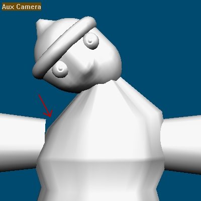
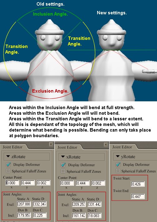
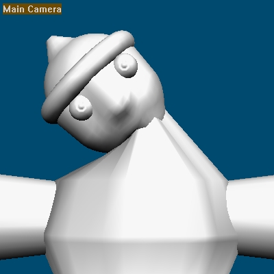
With your figure in the scene, open the Joint Editor. Select the head, select the zRotate parameter in the Joint Editor. You need to pull the red arms of the zRotate icon upwards so that the point where the arm meets the chest is within the Exclusion Angle. That fixes one problem, but the head is still distorting when it is zRotated. If you pull the green arms down until they are horizontal it will lessen the distortion of the head.
We also need to make similar adjustments to improve the xRotation. Again widening both the exclusion angle and the inclusion angle.
The head twist (yRotate) is also poor, and needs improvement. We need to move the Twist End down, so that only a little bit of the head at the very bottom twists, we can also move the Twist Start down so that there is more twist in the top of the chest.
See the image above for the head settings.
To be continued...
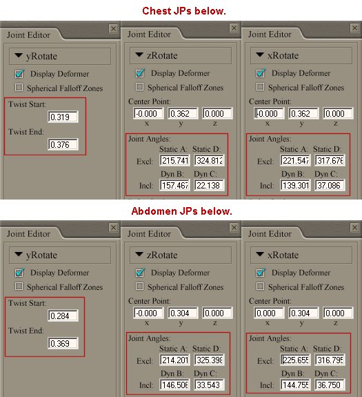
The chest and abdomen.
First off let's save the figure as it is at the moment to the Figures palette, so we don't don't loose the work we have done so far if something should go wrong at a later stage. Save it as "Robot-C-04". There is no easy way to undo changes we make to the joints, so it is best to do incremental saves of the figure so we can revert to a previous version if something gets messed up.
If your version of the figure turned out the same as mine, then the chest JPs are essentially upside down. The graphic above shows the settings I used for the chest and abdomen.
yRotate is the twist parameter for the chest. To my mind it seems to work best with this particular figure if the Twist End is set fairly low in the chest so that the part of the chest above the arm pits does not twist (this is just a personal opinion). Setting the Twist start about three quarters of the way down into the abdomen will extend the area twisted and thus give a smoother more spread out twist.
For the abdomen the Twist start has been moved down about one third of the way down into the hip, and the Twist End has been moved up slightly into the chest. Again this has been done to to give a smoother more spread out twist.
Save the pz3 (scene) ready to start again on the next step. Then you will probably want to try out the figure to see how the changes you have made work. After testing how the figure bends, an easy way to make sure that all the bends are set back to zero is to use the "Zero Figure" button in the Joint Editor, but note that this only zero rotations, it will not zero any translations that have been applied to the hip or BODY.
To be continued...
Quote - does this work for every character you make?
The same basic process can be used to create and rig any figure. However the details of the placement of the joint centers and the values used for the joint parameters will be different for every figure.
In this tutorial we created the figure (cr2) by using the Poser Hierarchy Editor. There is also a PHI file method for creating the figure, and two or three other methods. For conforming clothing the rigging is often copied from the character figure that the clothing is to conform to, then modified as may be necessary. I won't go into any of that, as it would take us too far off track. Which ever method you use to create the figure and do the rigging the end result is the same.
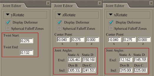
The thighs.
At the moment if you zRotate a thigh outwards the hip deforms badly. This is because much of the hip falls within the Transition Angle. To improve the bent shape of the hip when the thigh is zRotated, we need to exclude most of the hip from the Transition Angle. Sometimes the best settings for bending a joint in one direction are not the best for bending it in the opposite direction, and in such cases a compromise that you can live with must be found. This is one of those cases. For bending the leg outwards it would have been better if I had brought the inner exclusion arm down more, but if I had done that the thigh would have looked worse when the leg was bent inwards.
Set the parameters for the rThigh as in the image above. Do Memorize Figure (Alt+Ctrl+F). Then from the Figur menu do, Symmetry > Right To Left, answer "Yes" when prompted to copy the joint zone's, that will mirror the JPs to the left thigh. Do Memorize Figure again. Save the scene ready for the next step.
To be continued...
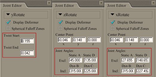
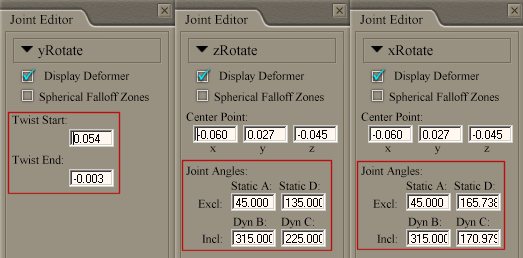
The feet.
I see that I made a mistake back in the step where we set the rotation order for the joints. The feet should have been YZX. Change that now, in the Joint Editor set the rotation order for each foot to YZX.
Use the settings shown above for the rFoot. Memorize the figure, use Symmetry Right to Left, to mirror the settings to the other foot. Memorize again. Save the figure to the Figures palette as "Robot-C-05". Save the scene.
To be continued...
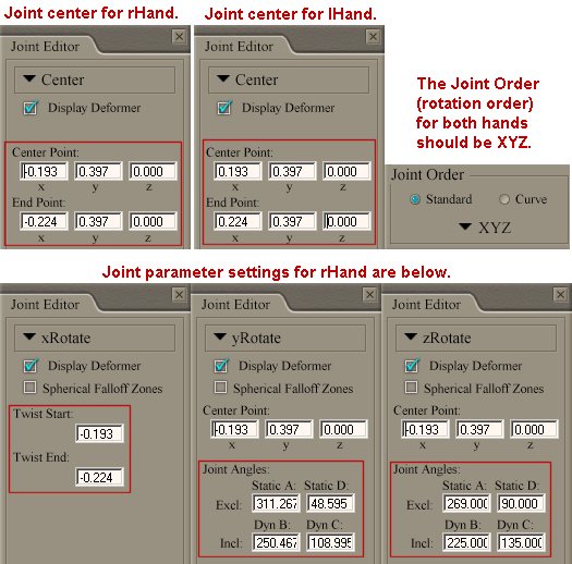
The hands.
We have not touched the hands or fingers yet. In the Joint Editor, set the Joint Order for both hands to be XYZ.
Because of the way this particular mesh reacts, I think it looks best to have all the bending for zRotate in the hand, and none in the forearm. Thus I have set both red arms of the zRotate icon to be aligned vertically, so that the exclusion angle covers all the forearm.
With the yRotate (side-side) bending of the hand I have taken a different approach, putting more of the bend in the forearm and less in the hand. Again this is just based on a personal opinion of what seems to work best to my eye. The settings I used are in the image above.
As in the previous steps, you should Memorize Figure, use the Symmetry Right to Left command to transfer the joint settings to the other hand, then save the scene to disk.
To be continued...
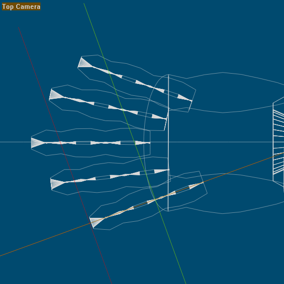
... Continued.
The fingers, part 1.
This is a big step because there are a lot of fingers, but we are nearing the end now, with only the fingers, eyes, and IK chains left to do. In most human figures the each finger is split into three groups, so there are thirty joints in all to deal with. In the current figure each finger is one group, so we only have ten joints to deal with. If you don't want to do the work of rigging ten fingers, you can just lock them, and skip this step. But if you are game, make a big pot of coffee and we will begin.
Set the Joint Order of each finger on each hand to be XYZ. As you do each finger, also set the y Center Point and End Point to be 0.397. To save typing, you can copy that value to the clipboard, and paste it into each finger. Get a nice close view of the rHand in the Top Camera, so it will be easy to select each finger in turn with the mouse. Once you have done the rHand, change the sign of DollyX for the Top Camera, and it should be in the correct position to do the lHand.
Set Document Display style to Outline. We need to set the x and z values for the Center Point and End Point of each finger on the rHand. The center Points need to be where the finger meets the hand, and the End Points should be at the tips of the fingers. Still looking through the Top Camera, use the mouse to drag the Center point and End Point of the rFinger1 to the correct location, then click the Align button in the Joint Editor. It should look like the image above. Repeat the same procedure for each finger on the rHand, setting the Center Point where the finger meets the hand, and the End point at the tip of the finger, then click the Align button. You have a little bit of tolerance, it does not need to be absolutely exactly correct.
Memorize Figure, use Symmetry Right to Left to mirror the settings, Memorize again. Save the scene.
To be continued...
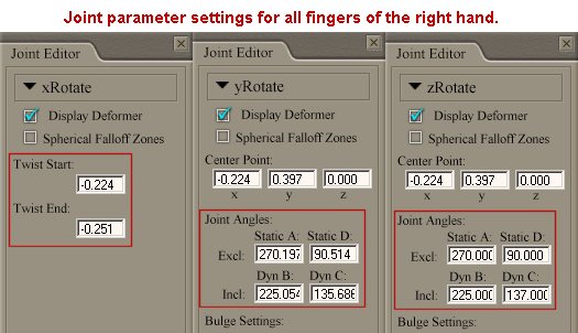
The fingers, part 2.
In the previous step we set the Joint Order (rotation order), and Center and End Points. In this step we will adjust the bending of the fingers.
Use the values from the image above, the same values for each finger of the rHand. I find the easiest way to do this is to rig the rFinger1 first, then copy the value for Twist Start of xRoate to the clipboard, then select each of the remaining four fingers in turn and paste the value into the Twist Start numeric field of each finger. Then select rFinger1 again and copy the Twist End value, and paste it into all the other rHand fingers, then back to rFinger1 and copy the value for Static A in yRotate, and paste that into the other fingers, and so on until you have copied all the values for the three rotations.
When all the fingers have been rigged, do Memorize Figure, do Symmetry Right to Left, and do Memorize Figure again.
Save the figure to the Figures palette as "Robot-C-06". Save the scene.
Test the fingers to make sure they are bending correctly. If they are you are ready for the next step.
In this step we used the same values for each finger, and this gave perfectly correct results for yRotate and zRotate. xRotate is the Twist parameter in the fingers, and strictly speaking this should have used different values for different fingers, but real fingers don't twist, so there is no such thing as a realistic finger twist. However if you do want to make the finger twisting more consistent (I wouldn't bother personally), set the twist start of each finger to the same value as the x Center point, and the Twist End to the same value as the x End Point.
To be continued...
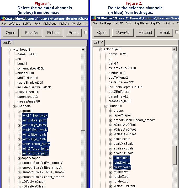
The Eyes, part 1.
The eyes are something of a special case, and there are various ways of dealing with them. The Center Point of the eyes should , naturally enough, be in the exact center of the eye. The End Point should usually be directly in front of the Center Point, at the front surface of the eye.
Most of the stuff that the joint parameters do is related to deforming an actor and/or its neighbouring actor when that actor is rotated. This provides smooth, rather than sharp bends at the joints. We don't want that with the eyes. We don't want the eyes to deform when the head is rotated, and and we don't want the head to deform when the eyes are rotated. So JPs that were our friends in the elbows and knees, are our enemies in the eyes. Try yRotating one of the eyes, see what happens to the head. :o
We are going to edit the cr2 to remove the offending channels, we will also remove some channels relating to the Torus (head band), for similar reasons. Whilst this can be done in a text editor, it is easier to use a cr2 editor. In this tutorial I'm going to use the free cr2 editor "CR2Builder", but you can use any CR" editor "CR2 Editor 1.51" (free), or "Poser File Editor" (commercial), are two alternatives.
Open the "Robot-C-06.cr2" in CR2Builder (or some other cr2 editor). Immediately resave it as "Robot-C-06.cr2" to the same folder.
Each actor will be listed in two locations in the window (Left TV), find the second occurrence of "actor head:1" (the number may be different) and click the "+" next to the head to expand it. Now click the "+" next to "channels" to expand that section. Hold down the Shift key and click on "twistY rEye_twisty", still holding down the Shift key, click on "jointX Torus_jointx", release the Shift key. You should now have the same range of channels selected as in Figure 1 above. Press the Delete key to delete them.
Scroll down to actor "rEye:1", click the "+" to expand it, then click the "+" next to "channels" to expand that. Select the three channels as indicated in Figure 2 above, and press the Delete key.
Scroll down to "lEye:1", expand the actor and channels sections. Delete the same three channels as you deleted from the other eye.
Save the file. Load Robot-C-07 in Poser (you may need to swap to a different library pallet, then back to New Figures, before you can see Robot-C-07 in the palette). Test the rotations of both eyes, they should no longer deform the head. Also test the rotations of the head to make sure they are still working.
To be continued...
Still here les. I'm up to the rigging for the hands and all is well but my internet connection has been really haphazard the last little while so that's why I didn't reply earlier when you asked if all was going well with us following along. I can see why 3 jointed fingers could be a real pain to rig. Again; thanks for all your hard work and fine explinations.
pdg
...Continued. The Eyes, part 2.
In a new blank document, load the Robot-C-07 figure you saved in the last step.
The eyes are not positioned symmetrically in the head.
We need to place the Center Point of the lEye in the center of the eye geometry, so that the eye rotates correctly. First get a close view of the head in the Top Camera. Set the Figure Display Style to "Outline". Set the Element Display Style of the lEye to "Smooth Lined".
Select the lEye, open the Joint Editor, set the horizontal center the green cross-hair on the eye, this should be a value of about x = 0.017. Set the x value of the End point to the same value. It was only the horizontal alignment that was out, the x and z alignment should be OK. Memorize the figure. Resave the figure to the Figures palette use the same name "Robot-C-07"
At the moment the translate dials for the eyes are hidden, you may want to unhide the translate dials so you can change the position of the eyes. There two ways we could unhide them, we could edit the cr2 to change the line "hidden 1" in each translate channel of each eye to read "hidden 0". Or we can use a pose file to unhide the dials in Poser. Here is the pose file:
{
//EyesShowTranDials.pz2
version
        {
        number 3
        }

actor lEye
        {
        channels
                {
                translateX xtran
                        {
                        hidden 0
                        }
                translateY ytran
                        {
                        hidden 0
                        }
                translateZ ztran
                        {
                        hidden 0
                        }
                }
        }
actor rEye
        {
        channels
                {
                translateX xtran
                        {
                        hidden 0
                        }
                translateY ytran
                        {
                        hidden 0
                        }
                translateZ ztran
                        {
                        hidden 0
                        }
                }
        }
}
To be continued...
...Continued.
Adding IK chains.
With the figure loaded in Poser, open the Hierarchy Editor, scroll to the bottom, you should see "IK Chains" click on that to select it. The "Create IK Chain" button at the bottom of the editor should become active, click on that button. Set the name as "Right Leg" and click OK. Scroll to the bottom of the window, there will be a new IK chain entry "Right Leg". In the editor drag the rThigh, and drop it on the "Right Leg" IK chain, then drag and drop the rShin on to the IK chain, then the rFoot.
Click the "Create IK Chain" button again, name this chain "Left Leg". Drag and drop the lThigh, lShin, and lFoot, on to the "Left Leg" IK chain. Always start at the part nearest the hip and work outwards, the last actor dropped on the IK chain will become the Goal Actor. Do the same thing for the arms, first drag the Shoulder, then the Forearm, and finally the hand.
Zero the figure in the Joint Editor, check the hip and BODY actors to make sure the translations are zero, then save the figure to the Figure pallet as as Robot-C-07.
To be continued...
...Continued.
Location of the obj file.
The method we used to create the figure made a new obj file and placed that file in the same folder as the cr2. Commercial figures store their obj file under the "Geometries" folder. If you want, you can do that too, I would certainly recommend that for any figure that is for distribution.
The process is reasonably simple. Create a folder for the obj, say for example:
RuntimeGeometriesakura_Robot
Move (or copy) the obj to the new "Robot" folder. Open the cr2 in a good text editor (I use EditPad Lite), or a cr2 editor.
There are two lines in the cr2 that start with the word "figureResFile" these two lines are both the same, and they tell Poser where to find the obj file. Currently those lines in the cr2 probably read like this:
figureResFile :Runtime:libraries:Character:New Figures:Robot-C-02.obj
Just edit those two lines to reflect the new location of the obj file, for example:
figureResFile :Runtime:Geometries:akura_:Robot:Robot-C-02.
If you want, you can also change the name of the obj file, so long as you remember to use the same new name in those two lines in the cr2.
To be continued...
...Continued.
Your figure now has a basic rig. There is a lot more that can be said about rigging a figure, but I neither have the time not the expertise to write a definitive work. My intention was only to provide you with the very basics, and that has now been done. However there are still a few loose ends to wrap up. And a few more things that you should know.
In this tutorial we have dealt with "Joint Centers", "Joint Order", and "Joint Angles", and not much else. You may have noticed boxes for "Spherical Falloff Zones" and "Apply Bulges". Neither of these are much use in the current figure, but that is due the the topology of this particular mesh. "Spherical Falloff Zones" at least, play a big role in most humanoid figures. So I feel I should at least give you a little idea of how they work. Though to be honest I do not have a good understanding of them myself. Take what follows with a pinch of salt, I may be mistaken on some points.
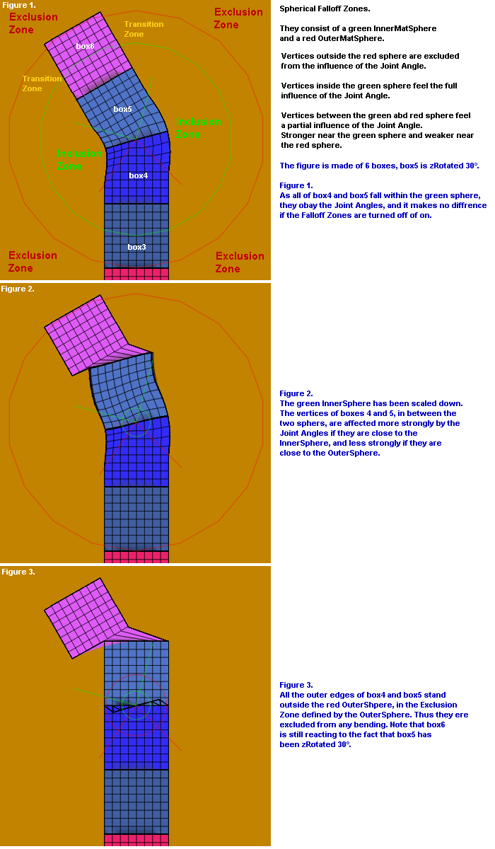
The arms of the icons for the Joint Angles only extend out so far from the actor, but the actual influence of the angles (inclusion Angle, Transition Angle, and Exclusion Angle) extends out to infinity. Spherical Falloff Zones are a way of limiting the area affected by the Joint Angles.
When we created the figure in the Hierarchy Editor, Poser automatically added Falloff Zones for each Joint Angle, but these zones are not positioned, their translations being set at 0 0 0, and they are disabled by default. There are two parts to the Falloff Zones, a green "InnerMatSphere" and a red "OuterMatSphere". When the zones have been enabled, and the relevant channel is selected in the Joint Editor, the Spheres can be selected from the drop-down props menu, or via the mouse cursor.
In a way the functioning is similar to the Joint Angles, inside the green Inner Sphere is an inclusion zone, outside the red Outer Sphere is an exclusion zone, and between the red and green spheres is a transition zone. Note that everything inside the Exclusion Angle will still be excluded, even if it falls within the green Inner (inclusion) Sphere!
To be continued...
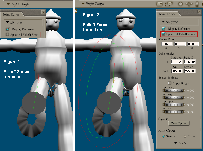
Let's think about a practical example of using Falloff Zones. If we xRotate the rThigh of the figure so that it stands out in front, you will see that this has an influence across the whole hip. We could use Falloff Zones to limit this influence to the right side of the hip only.
In Figure 1, the Falloff Zones are turned off. In Figure 2, the Falloff Zones have been turned on, and scaled and positioned to minimize the influence of on the left side of the hip. This is just an example of the sort of thing Falloff Zones can do. You may want to experiment with them, or you may decide not to use them, it's up to you.
To be continued...
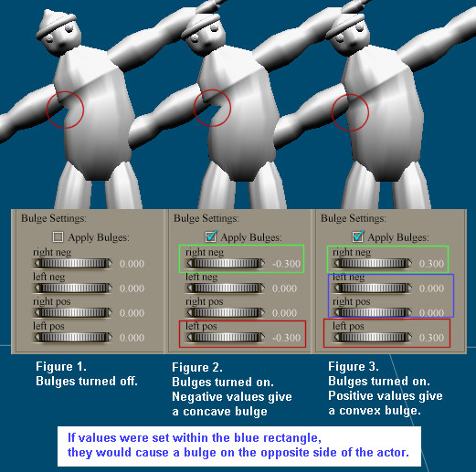
Bulges.
Another feature of the joints that can be turned on is "Apply Bulges". These are used to make an actor bulge in or out when that actor is rotated. In the image, the red rectangle represents the bulge setting that is currently active for the figure above it, the values in the green rectangles have no effect at the moment. If the chest were bent in the opposite direction, the values in the red rectangle would have no effect on it, but the value in the green rectangle would have an effect.
To be continued...
smoothScale and propagatingScale.
This step (like the previous two) is optional, if you don't think you will be scaling individual actors, you don't need to do it.
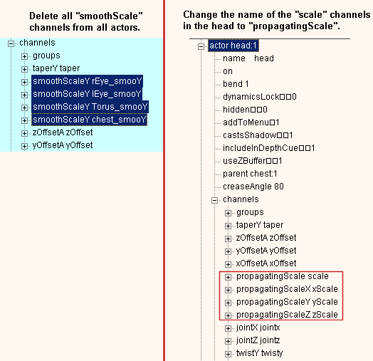
In the Joint Editor, in addition to the center and rotate channels, you will also see channels with the word "scale" in them, these are the "smoothScale" channels. If you inspect the cr2 in a cr2 editor (or text editor) you will see channels with internal names like "smoothScaleY rEye_smooY". When an actor is scaled a "smoothScale" channel can cause it's neighbouring actor, or some part of it's neighbouring actor to scale in response.
Load the figure. Scale its left shoulder, see the effect! Restore Element (Ctrl+E), then scale the right shoulder, Restore Element (Ctrl+E). Now scale the chest.
All the strange and mostly undesirable effects you see are caused by the smoothScale channels. We could try to adjust all of the smoothScale channels to give more desirable effects, but in my humble opinion smoothScale channels often cause more problems than they solve. I'm going to recommend that you delete all the smoothScale channels from the cr2, except those in the fingers, which do not seem to be causing any problems. You can do that in a cr2 editor. It is a rather tedious job, but I think it is worth it. Just go through each actor in the cr2, and delete any channel who's name starts with "smoothScale" (except in the fingers).
Keep a copy of the figure with the smoothScale channels still in it, and compare how the parts scale with the copy that the channels have been removed from. I think you will find that the latter is a big improvement.
When we scale the head, it would be nice if the eyes and Torus (head band) scaled with it. We could have tried to achieve that with the smoothScale channels, but there is another way. In a cr2 editor (or text editor), find the head actor, in the head actor find the channel named "scale scale". Change that line to read "propagatingScale scale". Add "propagatingScale" to the name of the other three scale channels in the head, so that the head now contains channels named:
propagatingScale scale
propagatingScaleX xScale
propagatingScaleY yScale
propagatingScaleZ zScale
What this does is to cause any children of the head (the eyes and torus0 to scale by the same factor as the head.
To be continued...
...Continued.
The tutorial has to end some time. So this is it! I hope you have found it of help.
Rigging figures well is a difficult job, and takes time. I am no expert at it. The various settings I have used in the joints should be looked at as rough approximations. If you spend some time experimenting, I'm sure you can improve the rigging.
The settings for the joints are only one factor in how well a figure bends. The topology of the mesh, the number, position, and shape of the polygons, is another very important factor. Also important is where the boundaries between the groups fall.
You may ask how I learnt what little I know about rigging. The answer is partly through looking at how other figures are rigged, but even more by experimenting. Just changing things on relatively simple figures, like the P3 and P4 nude people, and seeing what the effect of those changes was. And also by creating very simple figure out of two, three, or four box props, and trying things out on them.
If you have any questions, I will try to answer them. But in truth, what I have put in this tutorial is just about everything I know about rigging.
**The End!
**
Thank you very much for this les. You have done a masterful job of explaining the process. If the manual was only as good.
pdg
p.s. Sorry I seem to have disappeared but I just got my internet back. Local construction severed my connection a few blocks away and it took folks a while to find and repair the problem

- 1
- 2

Privacy Notice
This site uses cookies to deliver the best experience. Our own cookies make user accounts and other features possible. Third-party cookies are used to display relevant ads and to analyze how Renderosity is used. By using our site, you acknowledge that you have read and understood our Terms of Service, including our Cookie Policy and our Privacy Policy.
I ran into a problem i got the higharcher open but for some reason when i take off figure set up his left arm gets deleted but only his left arm the other parts are fine