Morkonan opened this issue on Feb 12, 2009 · 77 posts
Morkonan posted Thu, 12 February 2009 at 6:45 PM
This is a followup to a previous thread located here:
http://www.renderosity.com/mod/forumpro/showthread.php?thread_id=2762879 poser = cylinder h8tr >:(
In the course of discussion, the idea of backfacing normals causing rendering problems came up. Along with this came the idea that some artifacts are the "clear" result of this and experimentation showed that even remapping the object would not remove the previous artifacts even if the normals were either fixed or stripped.
Well, that is not true. In fact, my conclusion "so far" is that you can fix some of these "ripping" artifacts caused in this situation by remapping the obect. Even importing the object with backfacing normals, in cases tested so far, will not yield any unexpected rendering artifacts. Of course, the backfacing normal will not render appropriately. But, the KEY point is that the artifacts you see in the following illustrations will be removed by remapping and, not just remapping using any type of UV Projection. You have to use an APPROPRIATE Projection Axis. However, for Flat Projection Mapping it doesn't matter what axis it is oriented on NOR does it matter how ugly and screwed up the UVMap is. As long as it's a Flat Projection, it will render without "unexpected" artifacts. (More on "unexpected" artifacts in the conclusion.)
I must preface the following with the fact that I am a novice modeler but, very enthusiastic and fairly versed in most basic subjects of 3D modeling. But, I am a good investigator of phenomenon and, this counts as such. However, there is in-depth technical knowledge that I do not possess which may apply in ways that are not apparent to me at this moment. So, one must weight the circumstantial evidence below with those facts in mind. Professionals and the truly initiated are encouraged to give their opinions and share their knowledge here.
(Normals Are Stripped Unless Otherwise Noted. All lights are default P7 Infinites, two of them active, White at different levels and they have not been moved between samples. All maps, unless noted otherwise, are default projections of their specific Projection style and described axis without alteration of the Vertices in the map.)
Illustration 1 - First, we take the original cylinder, strip its normals and its UVMap. Well, that renders fine. In the previous thread (see my post there) the cylnew.obj would not render without artifacts unless this was done. Specifically, the shadowing or "ripping" (as using the word "shadowing" is misleading imo) seen on the top was persistent

Cylinder 1) UVMap is stripped.
Cylinder 2) UVMap is the Original map supplied (Box projection/overlapping opposing faces I "think")
Illustration 2 - From the results of earlier experiments, also in that thread, I decided to explore the UVMap question. Here, we have a simple box projection on the remapped objects and a cylinder projection. BOTH still show artifacts. But, what is highly unusual is that the objects appear differently! They're NOT the same.

Cylinder 3) Remapped - Box Projection, (simple, overlapping)
Cylinder 4) Remapped - Cylinder Projection, Z-Axis
***(cont'd)
Morkonan posted Thu, 12 February 2009 at 6:45 PM
Illustration 3 - Here, we have a Spherical Projection UVMap and it's the last of our "3D" choices of UVMap Projection Primitives. Still, it's a no-go as artifacts are still present. HOWEVER, in the Flat Projection UVMap along the z-axis, there aren't any artifacts! Could this be the solution to the problem?

Cylinder 5) Remapped -Spherical Projection
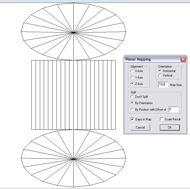
Cylinder 6) Remapped - Flat Projection, z-axis
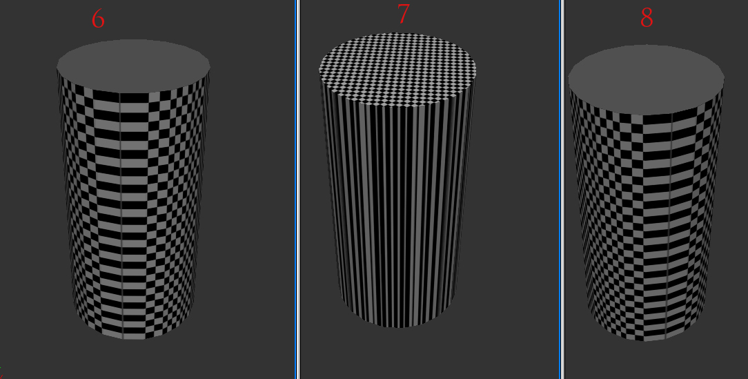
Illustration 4 - To explore the possibility more, I chose the other axis of projection as well. ALL yielded good results with no artifacts.

Cylinder 7) Remapped - Flat Projection, y-axis
Cylinder 8) Remapped - Flat Projection, x- axis
(cont'd)
Morkonan posted Thu, 12 February 2009 at 6:46 PM
Illustration 5 - Was this a property of the UVMap itself or a property of the Projection? After all, how much does it matter? Is the choice of Projection simply a matter of convenience for the person mapping the object? So, I wanted to see how much Poser cared about the UVMap. Which was more important in regards to these artifacts - Was it a nice UVMap or was the Projection more important? So, I murdered a Flat Projection UVMap and turned it into spaghetti. Still, the object rendered without artifacts. Poser cared more about the Projection method used than it did about the condition of the UVMap in regards to these artifacts.

Cylinder 9) Remapped - Flat Projection, z-axis, bad quality UVMap
Illustration 6 - So, how do the results compare on this specific object? Remapping the cylinder to a Flat Projection fixed the artifacts apparently caused by previous bad normals and improper UVMapping.

Cylinder 2) UVMap is the Original map supplied (Box projection/y-axis I "think")
Cylinder 10) Remapped Original, Flat Projection, z-axis (IT'S FIXED!)
(cont'd)
Morkonan posted Thu, 12 February 2009 at 6:47 PM
Illustration 7- But, since those artifacts have always been associated with bad/inverted normals or other mesh concerns, was my "fix" just a result of the bad normals being absent? In other words, was this just a correlation and not, as it would appear, a causation? Apparently, not in this specific case.

Cylinder A) Original Cylinder, Not Remapped, Normals Imported
Cylinder B) Original Cylinder, Remapped (FLAT Projection), Normals Imported
What is happening here?
An object with normals reversed improperly resulting in backfacing polys in Poser will cause the face to "disappear." That much is obvious and well known.
However, that does not, necessarily, result in the "ripping" effect we see in smooth shading on the object. As we can see in Illustration 7, a properly projected UVMap will "fix" that problem in this case even if there are backfacing polygons present. Moreover, implied by Illustration 5, it doesn't necessarily matter what condition the UVMap was in as far as this artifact effect is concerned - Only that it was the proper projection choice for that object.
In the case of the original object, as demonstrated in Illustration 8 below, a "Box Projection" was the worst choice possible out of all possible "primative" UV Projection Maps. That, obviously, made it appear as if the inverted normal was the issue. But, it was not. The issue was the projection choice and not the inverted normal. As we can see in Illustration 6, there are no unexpected artifacts and, what's more, the only artifacts apparent are small, blurry, "smoothing" artifacts on the edge where the inverted-normal-polygon joins with the flat top of the cylinder. Why are there unexpected artifacts there? Because, smoothing is determined by the vertice normals and those are a function of the average of the face normals for faces that connect to them. It would be understandable for those vertice normals, and hence the smoothing, to be somewhat confused or distorted. Those are "expected" artifacts due to the normals issue and the smoothing angle, IMO. "Unexpected" artifacts like the ripping effect we witnessed are now no longer "unexpected." They're a choice of a bad projection choice hence, they are now "expected" for this type of object.
Not every object is the same, obviously. Your results may differ from object to object. **The most important point here is that the projection method you use when first projecting a UVMap does make more of a difference than just a matter of convenience when beginning to UVMap. ** It CAN affect "ripping" artifacts in your model both in Preview mode and in the final Firefly render in Poser.
Morkonan posted Thu, 12 February 2009 at 6:48 PM
Implications:
Illustration 8 - A new cylinder with Cylindrical, Spherical, Cube and Planar projected UVMaps in x,y,z and, in the case of the Cube, overlapping all, overlapping facing and no overlapping UVs. Each row of three Projection orientations is flanked by a symbol of its map style. The choice is clear here - USE FLAT PROJECTION MAPS. :)

What are the Implications here?
Choosing the correct Projection for your UVMap is a critical decision. It can not be ignored or downplayed. Often, even in tutorials, I have heard the authors base their choices on whatever the most convenient Projection is to produce a decent looking UVMap to start with. As we can see in Illustration 5, the actual appearance of the UVMap does not matter as far as these ripping artifacts are concerned. You could have the most beautiful UVMap or a UV-Trainwreck and it wouldn't affect a change in these artifacts. (In THIS experiment.) Choosing the Proper projection for your UVMap is critical if you wish to avoid these ripping artifacts.. After all, once you have selected that choice any further work is going to be wasted if you decide to change it and have been tweaking UVs by hand.
Flat mapping, in my opinion, is always desired wherever possible as being the least likely to produce ripping artifacts. I've always preferred to use them and, now that I think on it, the ONLY times I have encountered ripping artifacts was when I did not use a flat projection. However, that's not saying much as I don't model inorganics very often (strict box/cylinder/sphere/linear-symmetrica-type shapes) and am in the habit of using planar maps already.
3) Because of the many choices available, there were some experiments I haven't done yet. In particular, the choice of shading regions/material zones and their borders, multiple-mapped objects, widely different shapes, bad UVmaps for all projections, etc.. The permutations of possibilities with multiple projection choices and almost infinite variety of objects is endless. So, this is not definitive by any means and should only be considered experimentally validated for the experimental object investigated - The simple cylinder. It also doesn't take into account someone's tenacity and tweaking, prodding, pulling and distorting a UVMap - It's possible they could "correct" the issue by some random spaghettifying of their improperly projected UVMap. I dunno... Investigating that takes too much work and I'm allergic to that...
In all cases, across all tests, the Flat Projection method yielded results without artifacts 100% of the time. The best any other method provided, with this object, was a 30% success rate. Does this apply to other models as well? As far as the ripping artifact is concerned, I believe we can say with some confidence that it would. Certainly, I think we can conclude that choosing an improper Projection map for an object could have similar results and ripping artifacts could occur.
I leave the rest to the reader to decide. There are those much more knowledgeable than I with professional experience and training that may have technical knowledge that would be valuable here. I am only a hobbyist intrigued by a troublesome question and have attempted to provide an answer for it as best I can with the knowledge I have gathered so far.
I'll continue investigating this type of artifact in other objects, other maps and across as wide a spectrum as possible of common uses for Poser and the topic of modeling for Poser.

dorkmcgork posted Thu, 12 February 2009 at 7:33 PM
excellent post
go that way really fast.
if something gets in your way
turn

bagginsbill posted Thu, 12 February 2009 at 8:22 PM
Very nice work.
I can't offer any insight, other than "that's impossible". :)
I don't know too much about mesh representations, but as far as I know, the UV coordinate initial projection is not something that ends up in the object. That's just an initial set of values to choose. It begs the question: Suppose I were to start with a flat projection, and then using my UV editing tools, I hand-move every vertex to the position that WOULD have been assigned by one of the other 'bad" projections. Would it now be bad or good? We'll never know, because nobody could ever move them with that kind of precision by hand, I suppose.
Renderosity forum reply notifications are wonky. If I read a follow-up in a thread, but I don't myself reply, then notifications no longer happen AT ALL on that thread. So if I seem to be ignoring a question, that's why. (Updated September 23, 2019)
Khai posted Thu, 12 February 2009 at 8:43 PM
Could we see UVtemplates on these "Flat projected' Cylinders please? a grid tells us nothing about how they are mapped.
Morkonan posted Thu, 12 February 2009 at 9:15 PM
Quote - Very nice work.
I can't offer any insight, other than "that's impossible". :)
I don't know too much about mesh representations, but as far as I know, the UV coordinate initial projection is not something that ends up in the object. That's just an initial set of values to choose. ...
:)
I know. It doesn't seem possible. But.. there it is. As far as an object being UVMapped, it either is or it is not. The UVMap travels with the .obj.
Illustration 9 shows a borked up UVMap which was first generated using a Flat projection. (2d planar projection.) The iterations I tried of distortions had no effect in producing ripping artifacts. The one pictured is just the one I saved.
Quote - It begs the question: Suppose I were to start with a flat projection, and then using my UV editing tools, I hand-move every vertex to the position that WOULD have been assigned by one of the other 'bad" projections. Would it now be bad or good? We'll never know, because nobody could ever move them with that kind of precision by hand, I suppose.[
I'm going to try that next along with experimenting with different UV Projections to both reproduce the effect and attempt to correct it staying within the UV map itself.
Morkonan posted Thu, 12 February 2009 at 9:22 PM
Quote - Could we see UVtemplates on these "Flat projected' Cylinders please? a grid tells us nothing about how they are mapped.
Sure. I'll archive the objects as well and post a link to a download. I didn't include the objects earlier because I used a different notation that wasn't referenced here in order to keep track of them. ie: cyl1-n1-uv2-x = Original cylinder, normals exported, uv2 (projection type), x-axis, etc.. Redoing that at the moment was cutting into dinnertime and my stomach demanded my hands be involved in food-transport instead of file-transport.
Give me some time to renamed/archive them and I link them for examination. I'm interested in finding out the cause and the solution to the problem even if I'm proven wrong. :) I'll post some of the uvmaps in a followup post as well as soon as I can export them and put them together.

TheOwl posted Thu, 12 February 2009 at 9:31 PM
Sorry dude. Still have the artifacts.
Passion is anger and love combined. So if it looks
angry, give it some love!
TheOwl posted Thu, 12 February 2009 at 9:32 PM
Passion is anger and love combined. So if it looks
angry, give it some love!
TheOwl posted Thu, 12 February 2009 at 9:41 PM
Passion is anger and love combined. So if it looks
angry, give it some love!
Morkonan posted Thu, 12 February 2009 at 10:04 PM
Quote - Could we see UVtemplates on these "Flat projected' Cylinders please? a grid tells us nothing about how they are mapped.
Here are the maps of the cylinders, as requested. The number corresponds with their number in the above illustrations.

As you can see, it appears the maps make little difference even if they are very similar. As noted in the original posts, no maps were altered from their "basic" projection format. Of course, few would be suitable for image texturing with maps like that. They'd have to be tweaked. But, that's not the point of the experiment right now. Producing a nice, clean UVMap in each projection style WILL be my next focus. Given the results so far, I don't have a lot of hope that will result in clean renders without artifacts. Could it? Sure. But, gravity "could" turn off tomorrow. What I really want to know is "Why" there appears to be differences across projection types and these artifacts can be reliably reproduced on demand simply by choosing a projection type! As BagginsBill noted, this really "shouldn't be" the case. )ie: The "It's impossible." quote.) Yet.... here we are. There are the above renders. Here are the maps. I'm packing up the objects now.
However, one experiment doesn't mean anything unless it can't be falsified yet can be reproduced. So, reproduce the results! THAT is what I really would like to see.
In the last render I created my own cylinder in order to isolate the problem and demonstrate that it was not some weird artifact inherent in some portion of code in the original object file. I reproduced the very same results using my own cylinder. That SHOULD mean that anyone can reproduce these results. I used Hexagon and Poser 7. However, the original model was created in a program other than Hexagon so, we know that this crosses software boundaries in at least this instance.
So, create your own cylinder. Apply a different type of projection to several copies of it. Just use the default projection, don't re-arrange the verts for now, and then render them in Poser and see what happens. If you get similar results or even the same results, that's enough to verify that the effects can be reproduced. The next step would be "Falsification" of the experimental results or the interpretations/conclusions. We should, with the knowledge base here, be able to accomplish Falsification if it is possible. We most certainly should be able to easily accomplish Verification of the observed effects. Try it and see.
Morkonan posted Thu, 12 February 2009 at 10:07 PM
Quote - Okay I tried planar mapping my cylinder in uvmapper classic.
Sorry dude. Still have the artifacts.
Working on it now, will post results in a sec.
PS - That is NOT the same UVMap I have for the object you linked in the .txt file!
Opened with UVMapper (Classic)

Khai posted Thu, 12 February 2009 at 10:07 PM
ok I see where your going.. sorry you've gone a bit wrong :( 8 is only mapping 1 side of the cylinder. the tops, sides and back are not being mapped at all and being compressed into the edges of the mapping you've got... applying a texture to it would only work on that one side.
Morkonan posted Thu, 12 February 2009 at 10:18 PM
Quote - ok I see where your going.. sorry you've gone a bit wrong :( 8 is only mapping 1 side of the cylinder. the tops, sides and back are not being mapped at all and being compressed into the edges of the mapping you've got... applying a texture to it would only work on that one side.
No.
That's not how it works.
First of all, where are the "tops", "sides" and "back" of a cylinder in a flat projection map? That's determined by the axis and, even then, it's not appropriate to apply "top", "sides" etc.. terms to a UVMap in any meaningful way.
Notice, there are 10 faces of the vertical side of the cylinder depicted in map #8 projected along the x-axis. The cylinder has 20 facets around its circumference. The other 10 faces are stacked directly below these. The remaining 40 facets of the "top" and "bottom" are incorporated into long, stretched out UV lines stacked on top of each other which join everything into a cohesive whole map. They are hidden below the UVs as well. There are no "missing" facets that are not being mapped. They're simply not being mapped very well if you were going to apply a texture to them. But, they ARE all mapped.
Is it suitable for using for a texture that wraps around the side wall of the cylinder in one cohesive band and has separate details for the top and bottom? Not as it is presented, no. But, that's not the issue at the moment.
Morkonan posted Thu, 12 February 2009 at 10:33 PM
Quote - Okay I tried planar mapping my cylinder in uvmapper classic.
Sorry dude. Still have the artifacts.
What you used was not a planar projection. You used a "Cylinder with Cap" projection, I would assume. I linked what UVMapper Classic showed as the map for your cylinder in the above post. That is a planar map. Here is a Cylinder-With-Cap projection from UVMapper Classic (free) using your same cylinder. What you sent was obviously a Cylinder With Cap projected UV'd object.

The cylinder you provided was mapped with a Cylindrical projection and NOT a Planar Projection.
Here is a render in my original lights used in the experiment with your cylinder using the Cylinder With Cap projection (my assumption) you linked in your post and then one I did using a simple Planar projection.

Your cylinder as supplied is in foreground left, the one I remapped to use a Planar Projection is foreground right. The latter, Planar Projection Mapped Cylinder is free of artifacts. The former, Cylindrical With Cap Mapped Cylinder is not.
Khai posted Thu, 12 February 2009 at 10:44 PM
Quote - > Quote - ok I see where your going.. sorry you've gone a bit wrong :( 8 is only mapping 1 side of the cylinder. the tops, sides and back are not being mapped at all and being compressed into the edges of the mapping you've got... applying a texture to it would only work on that one side.
No.
That's not how it works.
First of all, where are the "tops", "sides" and "back" of a cylinder in a flat projection map? That's determined by the axis and, even then, it's not appropriate to apply "top", "sides" etc.. terms to a UVMap in any meaningful way.
Notice, there are 10 faces of the vertical side of the cylinder depicted in map #8 projected along the x-axis. The cylinder has 20 facets around its circumference. The other 10 faces are stacked directly below these. The remaining 40 facets of the "top" and "bottom" are incorporated into long, stretched out UV lines stacked on top of each other which join everything into a cohesive whole map. They are hidden below the UVs as well. There are no "missing" facets that are not being mapped. They're simply not being mapped very well if you were going to apply a texture to them. But, they ARE all mapped.
Is it suitable for using for a texture that wraps around the side wall of the cylinder in one cohesive band and has separate details for the top and bottom? Not as it is presented, no. But, that's not the issue at the moment.
whats the point in fixing the artifact if leaves you with a mesh you can't put a map onto?
TheOwl posted Thu, 12 February 2009 at 10:52 PM
The first image I gave you is what the mapping of the cylinder looks like when loaded in UVmapper Classic. At the right, I showed the settings I took for planar mapping.
It turned into vertical rows just like what you shown with the caps hidden. The obj I posted is already planar mapped. When I imported it to poser. The artifacts are still there.
Sorry for the confusion.
Whatever mapping software you are using. Its planar projection might have done something to it that took away the artifacts. Just like bagginsbill's blender import/export.
Passion is anger and love combined. So if it looks
angry, give it some love!
Morkonan posted Thu, 12 February 2009 at 11:13 PM
Quote - Markonan,
The first image I gave you is what the mapping of the cylinder looks like when loaded in UVmapper Classic. At the right, I showed the settings I took for planar mapping.
It turned into vertical rows just like what you shown with the caps hidden. The obj I posted is already planar mapped. When I imported it to poser. The artifacts are still there.
Sorry for the confusion.
**
Whatever mapping software you are using. Its planar projection might have done something to it that took away the artifacts. Just like bagginsbill's blender import/export.**
(No problem in regards to any confusion. If you are ever running low on "Confusion" send me a PM and I'll give you some of my surplus!) ;)
Hex may be inherently fixing this issue with your cylinder? That is VERY possible. However, the issue has moved to a much broader one.
While we know How your cylinder can be fixed, we don't know Why it can be fixed.
My aim was to try to figure out, exactly, "How" to fix such a problem and what conditions cause it. I think I can do that on demand now. But, I still don't know "Why" it behaves as it does.
It was suspected that the "ripping" artifact issue along the top of the cylinder was with normals. However, that doesn't appear to be the case. Notice in Illustration #7, the large render of a cylinder with a normals problem. Here, there is no "ripping" of shadows (could smooth shading maybe but, only if it has something to do with vertex normals or their generation from face normals averages). That problem was solved, as previous experiments support, with a choice of Projection Map and not a choice of splitting verts or otherwise scrubbing the model clean using another process.
So, while your cylinder is related to the issue, what it opened up for me is a new can of worms - Specifically, why are these models rendering differently with different projection maps and why does Planar mapping seem to correct every instance of "ripping?" Only in two occassions did other projections yield satisfactory results using their defaults, without manipulation. And, even bad UVMap manipulation (by hand) would not cause the Planar Projected UVMap have any ripping results whatsoever.
You cylinder was just the tip of the iceberg. :) Of course, it may just be an "ice-cube in a teacup" type of situation here considering I am not a professional in this field. I may be misinterpreting something or there may be something else going on I am not aware of. But, consistent and reproduceable experimental results tend to imply that there is something significant going on here that others may wish to be aware of.
Morkonan posted Thu, 12 February 2009 at 11:27 PM
I uploaded the objects to Rapidshare. It's only 13k but, I don't know how to embed text files in a post sooo.. Rapidshare it is. If it runs out of downloads (maximum 10) then I will re-up it to my account at ShareCG.
http://rapidshare.com/files/197476310/Packed.rar.html
I included the mtl and generated texture-checker files in case there is something there which sheds light on the issue. I think I got them all. Their names don't match the .obj files which I have renamed to match the cylinders depicted in the above illustrations.
Check them out and experiment and/or doublecheck my results. However, it'd be more useful if anyone could reproduce the same results using cylinders and Projected UVMaps of their own creation using a variety of different tools yet rendered in Poser.
Informed Criticism is important here. "Why" this is occuring is of primary importance. If you can shed light on it, falsify my findings, conclusions or reasoning, PLEASE do so!
Khai posted Thu, 12 February 2009 at 11:37 PM
which one is the 'flatmapped' one?

stonemason posted Fri, 13 February 2009 at 12:01 AM
maybe an easier fix is to detach the top & bottom in your modeler?..as in this obj exported from 3dsmax,it;s still one mesh but the top verts aren't attached to the middle ones
http://stefan-morrell.com/cyl_test3.obj
I dont think planar mapping a cylinder could be regarded as a fix,when it creates uv mapping you cant use.
it is an odd problem though,I tested myself & your right,with no uv mapping it loads without artefacts
Morkonan posted Fri, 13 February 2009 at 12:02 AM
Quote - which one is the 'flatmapped' one?
By "flat mapped" I mean Planar Projection. I wish I could change the use of that term in my above posts but, Renderosity's overly paranoid editing restrictions won't let me. :(
As far as which is the planar mapped one, refer to the numbered cylinders present in the above illustrations and match up their number with the cylinder number object file.
ie: cyl-6.obj through cyl-9.obj correspond to the Planar Projection mapped cylinders in various axis projections.
(Really wish I could change those terms to "Planar Mapped" and redo the descriptions.. sorry for the confusion there.)
Morkonan posted Fri, 13 February 2009 at 12:06 AM
Quote -
maybe an easier fix is to detach the top & bottom in your modeler?..as in this obj exported from 3dsmax,it;s still one mesh but the top verts aren't attached to the middle ones
http://stefan-morrell.com/cyl_test3.obj
I dont think planar mapping a cylinder could be regarded as a fix,when it creates uv mapping you cant use.it is an odd problem though,I tested myself & your right,with no uv mapping it loads without artefacts
However, you CAN use the mapping. It's not the UVMap itself that matters if you're concerned about this "ripping" effect- it's the projection style, apparently.
All you have to do is Planar Project the map and then edit it using seams, pins, manipulation or whatever other tools you have available to move the vertices around to get a map that is useable with textures. As long as it is still a planar projection, you should not have any of the "ripping" shadowy artifacts. That is, if everything here is entirely correct and all of these experimental results prove valid.
I didn't manipulate the UVs at all in these projections. I simply used the default map. But, I COULD have easily manipulated them, created seams, unfolded them differently, manipulated the vertices and so forth. I will be doing that in the next series of tests to see how they react and to see more specific effects regarding the artifact we see displayed in the above renders.
Morkonan posted Fri, 13 February 2009 at 12:14 AM
Quote -
maybe an easier fix is to detach the top & bottom in your modeler?..as in this obj exported from 3dsmax,it;s still one mesh but the top verts aren't attached to the middle ones
http://stefan-morrell.com/cyl_test3.obj...
An added comment:
Splitting vertices is not always a good option. For instance, if you try to put displacement maps on that cylinder, it's going to explode. It also increases the size of the file. For instance, that cylinder has 82 verts as it stands. If I weld it back together, it only has 42 verts. That's because the 40 additional vertices in the top and bottom (20 faced cylinder) are now combined with the face vertices. Smaller model memory-footprint = always good.
Also, some distributors like DAZ don't appreciate split verts when it is used for correcting rendering problems. They insist on people using additional edgelines to create sharp edges.
Well, what if you had a model where you were trying to correct this artifact? Instead of adding yet MORE geometry and/or removing the ability for you to use displacement maps and keeping any future user from adding their own displacement maps.. .all you might have to do is remap it using a Planar Projection! Wouldn't that be nice?
Granted, this same technique may not apply to sharp edges. Most likely, it doesn't as smooth-shading is NOT what we're looking at here. At least, not in the classic sense. But, having another tool that reduces the need for "corrective" geometry and gives consistent and very desirable results is always a "Good Thing." If Planar Projections end up being the solution to these problems, a LOT of what people have been using as corrective geometry to fix this issue is going to disappear - All they'll need to do is Planar Project their UVMap and go from there.
Khai posted Fri, 13 February 2009 at 12:19 AM
ok as I thought. sorry mate.. you've mirrored the mapping. the ends of the cylinders are not mapped at all and you've got a streatched seam down each side where the overlapping UVmap's meet.
this is what we actually try to avoid in UVmapping.
Khai posted Fri, 13 February 2009 at 12:21 AM
Quote -
maybe an easier fix is to detach the top & bottom in your modeler?..as in this obj exported from 3dsmax,it;s still one mesh but the top verts aren't attached to the middle ones
http://stefan-morrell.com/cyl_test3.obj
I dont think planar mapping a cylinder could be regarded as a fix,when it creates uv mapping you cant use.it is an odd problem though,I tested myself & your right,with no uv mapping it loads without artefacts
we know that fix ;) if you check out the other thread this was spawned from, we're trying to work out why we get the artifact and how to fix it.. and whether it is a bug that is in poser.
Morkonan posted Fri, 13 February 2009 at 12:21 AM
Quote - ok as I thought. sorry mate.. you've mirrored the mapping. the ends of the cylinders are not mapped at all and you've got a streatched seam down each side where the overlapping UVmap's meet.
this is what we actually try to avoid in UVmapping.
Which cylinder? (Object File name) are you talking about?
And "Yes" you'd want to avoid that if you were going to use that map for a texture. But, that isn't the point here. There are no "unmapped" faces in that object. (In any of them that have a UVMap. That's why they all had texture-checker png images attached to them - To check for that.) Put a texture checker on it.
PS - Better yet, open the object back up and relax the UVmap (if you have a tool that does that) along the bottom and top of the map. You'll see the vertices move and the mapped top/bottom/side of the cylinder will be more apparent.
Khai posted Fri, 13 February 2009 at 12:25 AM
numbers 6 7 8 in your zip.
and I DID put a checker texture on. that's how I saw each one was flawed in the mapping.
Khai posted Fri, 13 February 2009 at 12:31 AM
Morkonan posted Fri, 13 February 2009 at 12:35 AM
Quote - numbers 6 7 8 in your zip.
and I DID put a checker texture on. that's how I saw each one was flawed in the mapping.
Yes, the mapping is flawed if you were going to put a texture on it. But, that doesn't make a difference in regards to this particular artifact. There is no texture here to be distorted.
What's more, as seen in illustration 9 (IIRC) you can have even worse UVMapping and as long as it is done with a Planar Projection, that particular artifact will not appear.
These UVMaps were not done for texturing purposes. The quality of the UVMap in terms of applicability for a photographic texture does not appear to matter as far as this artifact is concerned. It is the Projection mode that seems to be having some sort of effect.
"Could" distorted UVMaps have an issue? Maybe. But, all the ones I have tried so far do not yield any artifacts as Illustration 9 (IIRC that is the correct number) shows. It has a badly done UVMap but shows no "ripping" artifacts at all.
Morkonan posted Fri, 13 February 2009 at 1:09 AM
Quote - just so we're clear - here's the cylinders with checkered maps applied.
I do understand what you are saying. The best way for me to communicate to you what I am saying is represented below:
1) Here is a cylinder with a horrible UVMap. However, that UVMap was first created using a Planar projection. It is rendered in poser with the default texture-checker mapped to it.

Here is the UVMap for that cylinder:

Here is the cylinder in Hexagon and I have selected one of the top faces so it is highlighted in the terribly done UVMap.

And, when you remove the texture to better see if there is any artifact present, this is what you get in Poser.

There is NO artifact present even with a horribly distorted UVMap in a Planar Projection. If you apply another texture image just in case you may think it is due to the absence of any texture, this is what you get:

(Concrete texture image mapped using that very bad UVMap)
There is no artifact present no matter how bad the UVMap is with a Planar projection from any axis. Texture or no texture, the artifact is absent. Other Projections vary in whether or not they will present an artifact on this object with Box Projections being the worst culprits and Cylinder and Spherical Projections only having one appropriate axis.
A UVMap is supposed to be used primarily for applying 2D images to 3D surfaces. Using procedural textures, generated by the computer, doesn't need a well done UVMap. The computer does not care about whether or not the information is understandable in two dimensions. For the purposes of texture mapping an image, we DO care and must have a 2D representation of a 3D surface in order to be accurate. That is WHY there are UVMaps.
They're not supposed to act this way and influence this type of artifact. That's what I'm getting at. It doesn't matter one bit regarding the quality of the UVMaps or their vertice locations on the included experimental objects in that collection or whether those maps are suitable for appropriately applying 2D images to a 3D surface with accuracy.

TrekkieGrrrl posted Fri, 13 February 2009 at 5:27 AM
Interesting.
And I agree, if you're using procedural textures/shaders, NO uvmap can often produce better results than a wrong UVmap (wrong considering the shape of the model)
I'm baffled that a planar map would be the best option here, but apparently, it is :)
Since my own Poser is tied up with a large render.. perhaps someone could try applying a checkered PROCEDURAL map to that cylinder? I'd like to see how the ends are looking.
FREEBIES! | My Gallery | My Store | My FB | Tumblr |
You just can't put the words "Poserites" and "happy" in the same sentence - didn't you know that? LaurieA
Using Poser since 2002. Currently at Version 11.1 - Win 10.
bagginsbill posted Fri, 13 February 2009 at 6:57 AM
I'd love to work on this too, but I'm swamped with real work, and I'm going on a ski vacation for a week. May or may not have internet. So I may be out of touch for a week, but keep going. This is very strange and interesting.
Renderosity forum reply notifications are wonky. If I read a follow-up in a thread, but I don't myself reply, then notifications no longer happen AT ALL on that thread. So if I seem to be ignoring a question, that's why. (Updated September 23, 2019)
richardson posted Fri, 13 February 2009 at 7:17 AM
Good stuff Morkonan,,
bm
TheOwl posted Fri, 13 February 2009 at 8:11 AM
I'm going on a ski vacation
and you call that work? LOL
Passion is anger and love combined. So if it looks
angry, give it some love!
Morkonan posted Fri, 13 February 2009 at 10:34 AM
Quote - Interesting.
And I agree, if you're using procedural textures/shaders, NO uvmap can often produce better results than a wrong UVmap (wrong considering the shape of the model)
I'm baffled that a planar map would be the best option here, but apparently, it is :)
Since my own Poser is tied up with a large render.. perhaps someone could try applying a checkered PROCEDURAL map to that cylinder? I'd like to see how the ends are looking.
Here ya go:

Using the "Tile" generator, rectangular shape, .1 tile width plugged into the diffuse color. Weird huh?
The thing is that what I'm trying to target, the shadowy "ripping" artifacts seen in the other cylinders, is (so far) not produced when using a Planar map. Moreover, the quality of the Planar map doesn't matter at all. As you can see, the quality of this UVMap leaves much to be desired. But, as long as it's not a measured pattern, it doesn't really matter, apparently. (I wonder if that is because of the way the units for a procedural pattern are calculated? Otherwise, the uvmap shouldn't matter, should it?)
Anyway, no artifacts yet with Planar projections but lots with other projection modes. Since this is problem I see posted on time and time again with lots of frustrated creators trying to get their objects to look appropriate, it definitely insists on further inquiry. I'd love this to solve some people's problems and save them the headache of splitting verts, adding corrective geometry (bevels), when trying to solve this particular type of issue.
*Just a Note on "smoothing" : I believe this is entirely different from "smoothing" issues where split verts and beveled edges are normally used. Vertex normals are the determiner there. Unless a UVMap is somehow interacting with the generation of vertex normals and that interaction is only dependent upon the initial Projection mode, then it's a somewhat unrelated issue. So, this won't keep edges sharp when the object is smooth shaded. (At least, I don't think it will.) But, it appears it will help to remove the ripping artifact that plagues many. More tests still to be done before it can be called "verified" though. I really need others to reproduce the effects to discount any application specific effects I may be experiencing before being more confident of the results.
Morkonan posted Fri, 13 February 2009 at 10:40 AM
Quote - I'd love to work on this too, but I'm swamped with real work, and I'm going on a ski vacation for a week. May or may not have internet. So I may be out of touch for a week, but keep going. This is very strange and interesting.
May or may not have internet?
OH NOES! Good Lord Man, that is a definite crisis! No intrawebz.... Shocking! You had better confirm this before you go and, if so, stock up on your intrawebz! Pack an extra suitcase if you have to!
Have fun, enjoy yourself and be safe. No intoxicated ski-jumping off cliffs or anything like that. Don't use the chair lift for a pull lift. Altitude is a negative forcer of survival unless you are in constant contact with the ground which is at the same altitude, or very slightly below it. Just a tip I picked up, use it in good health.
Morkonan posted Fri, 13 February 2009 at 10:45 AM
Quote - Good stuff Morkonan,,
bm
Thanks. But, can it be duplicated? Can others duplicate the same findings that I have? That's the big issue. If others can duplicate this specific interaction of Projection Mode and rendering artifacts in both realtime video (opengl/etc) and in the Firefly renderer when using Poser and UVs generated in multiple applications using the similar variation in Projection Mode then we have something to work with. If not, it could be an application specific issue with what I used to generate these UVMaps (Hexagon). That has to be isolated with greater confidence than it has so far.
I'm going to try to do that in the next series of tests by using UVMapper, Blender, Anim8tor and any other freebie package I have that may have the capability to produce Projection Map generated UVMaps. But, a third-party confirmation is what I am really hoping for - That will clinch it as not being a hardware specific artifact (my processor/OS/vid interacting with Firefly rendering or realtime rendering)
JoEtzold posted Fri, 13 February 2009 at 2:27 PM
Morkonan, just a idea.
Did you check the sort order of the uv values in the obj files with different projection modes on one side and with rearranging the uv in the planar mode on other side.
What do I mean.
I remember one of the purposes of STOMP. There was (is) a flaw in poser up to version 6. If in 7 I don't know at the moment.
If you have several material zones in a object, this may be saved as single divided parts as they are coming handy to the model app while saving.
If poser is reading such clustered materials it need's much much more time as if that material zones are saved together.
So STOMP as also the riptide object exporter for C4D (same author I guess) are saving that data sorted by material.
So this will change the sort order in obj file and that load's than quick as the wind.
May it be that such a ordering problem is touched here again.
Just as an idea. Poser isn't doing things a logical manner all the time, is it ?
Morkonan posted Fri, 13 February 2009 at 8:50 PM
Quote - Morkonan, just a idea.
Did you check the sort order of the uv values in the obj files with different projection modes on one side and with rearranging the uv in the planar mode on other side.What do I mean.
I remember one of the purposes of STOMP. There was (is) a flaw in poser up to version 6. If in 7 I don't know at the moment.
If you have several material zones in a object, this may be saved as single divided parts as they are coming handy to the model app while saving.
If poser is reading such clustered materials it need's much much more time as if that material zones are saved together.
So STOMP as also the riptide object exporter for C4D (same author I guess) are saving that data sorted by material.
So this will change the sort order in obj file and that load's than quick as the wind.May it be that such a ordering problem is touched here again.
- If you start with a planar map and later rearrange that map does this change the order while saving in object files.
- And is the sort order influenced depending which map mode you choose first ?
- If so what will happen if you arrange the sort order of a cylinder map like the order of the planar map. Ok, this have to be done by hand editing the obj file.
But than it could be clearer why map projection mode is of influence.Just as an idea. Poser isn't doing things a logical manner all the time, is it ?
Hmm, interesting idea. I'll do some file comparisons. As a matter of fact, I was planning on trying exactly what you just described but, not with as detailed a reason. I wanted to find a way to "remap" the object by hand using only the contents of the file in just such a way as you suggest. That way, I could try to change how the object's UVMap was projected without using a mapper to do it and see if there could be any interesting results. I'm also going to go overe the wavefront.obj file specification and check to see if there are any interesting file commands I can find. Another thought is to export in other formats besides .obj and see if these anamolies continue to appear in different projection mode. If not, it could be a clue as to why projection mode seems to matter so very much in this experiment.
I downloaded STOMP the other day and am also going to do some .obj tweaking with it to see if it might isolate the variables that are effecting these renders. I'll do the file contents comparison later this evening.

Spanki posted Tue, 24 March 2009 at 7:09 AM
After a brief scan of the topic and 2 mins of experiments, the 'issue' is clear...
The artifact you are seeing happens at "any uv-seam, around the cylinder". The reason that flat-mapping eliminates the artifact is because flat-mapping produces no uv-seam (no 'splits' between the vertical side polys of the cylinder).
Forget everything else and all other speculation related to Normals (Poser ignores any normals in the .obj file anyway), ordering and split vertices etc. This is a 'uv-seam' issue. One seam == one artifact. If you have 4 seams (ie. a Box Mapping), you get 4 artifacts. Zero seams (flat-mapping) == zero artifacts.
With that out of the way... I currently have no idea 'why' this is causing artifacts in Poser, but I'll give it some thought (I was on the way to hit the sack when I found this thread).
Cinema4D Plugins (Home of Riptide, Riptide Pro, Undertow, Morph Mill, KyamaSlide and I/Ogre plugins) Poser products Freelance Modelling, Poser Rigging, UV-mapping work for hire.
Spanki posted Tue, 24 March 2009 at 3:08 PM
Ok, so I haven't come up with a 'why' the artifact occurs (although it's likely some vestiges of the micro-polygon smoothing not fully being by-passed when smoothing is disabled.. more on this later), but since the problem DOES exist, it doesn't really matter 'why' for existing owners of the software - only how to avoid or work around it.
With the above in mind, here are my findings so far...
To start with, I created a conical-shaped cylinder (pinched at the top), just to help visualize the 'flat' uv-mapping type (and in the following images, the cone #2 has this mapping... mapped looking down from the top, as if draping a table-cloth over the cone). I was also checking / concerned with highlights and shadows and (of course) texture-mapping results (a 'fix' is not much of a fix if it ruins your ability to texture the object effectively).
In the following images, the cones are labeled 1-4 and have the following properties:
...ok, with the above legend in mind, let's move on to the images.
In each image below, the lighting is exactly the same with a shadow-casting infinite light from the above-rear-right and another infinite light (casting no shadow) from the front-mid-left direction.
The first one is a simple render, with no texture, so we can see the artifact and the fixes. It also shows how each handle the particular lighting setup...

Notes: - note the artifact on cone #1, but 'fixed' on the others
...ok, so the shadow and shading/specular made me curious if this was due to camera angle / cone position-relative, so I swapped the front and rear cones and rendered another...

...hmm, the specular changed a bit with the new positions, but the differences are still there and the shadow differences are definately not due to the positions. [for the rest of the images, I swapped the positions back to the original configuration].
The next image adds a texture, so we can see what we're working with...

Notes: - this image gives you a good visualization of the 'flat' mapping (cone #2), but keep in mind that the sides are sloped... if they were vertical, it would look much worse (with similar issues when mapping flat from one of the sides).
...ok, so far, all of these renders are with Polygon Smoothing disabled. Let's enable that and let the fun begin...

Notes: - Cone #1 - the overall resulting 'shape' of the cone (as rendered) is exactly the same as #2, but notice that where the 'artifact' is, ALSO effects the smoothing (the texture is now being distorted by the smoothing).
Conclusions:
Again, 'why' the artifact is happening is really only of concern by the programmers (who need to figure it out and fix it), so the question for the rest of us is knowing 'when' it's likely to occur (with capped cylindrical type objects, every place there is a gap/seam in the uvs of the sides) and how to work around it.
Except for cone #2, the rest of them use the exact same uv-mapping (a cylindrical-cap style mapping). The uv-mapping style is only important because of the number of resulting seams, so you can make the issue worse with other mapping projections (adding additional seams), but you can only make it better if there are no seams - a flat type mapping - but that just leaves you with texturing issues and does nothing for polygon smoothing issues.
Obviously you can enable/disable polygon smoothing to eliminate that particular problem, but that's not always convenient or desired.
That leaves us with the "bevel solution" and the "disconnect solution" (cones 3 & 4, respectively)... - They each add additional vertices, but the bevel solution also adds additional polygons.
...the "disconnect solution" seems to cover all the bases, but may or may not give you the shading and/or style you are looking for.
Cheers,
Keith
Cinema4D Plugins (Home of Riptide, Riptide Pro, Undertow, Morph Mill, KyamaSlide and I/Ogre plugins) Poser products Freelance Modelling, Poser Rigging, UV-mapping work for hire.
Spanki posted Tue, 24 March 2009 at 3:17 PM
Quote - ...ok, so far, all of these renders are with Polygon Smoothing disabled. Let's enable that and let the fun begin...
Notes: - Cone #1 - the overall resulting 'shape' of the cone (as rendered) is exactly the same as #2...
...I just noticed that the shadowing changed on #2 in the above image as well, so it may be that the overall (rendered) shape of #1 and #2 is actually different as well, but it's at least interesting that the shadowing changed.
Cinema4D Plugins (Home of Riptide, Riptide Pro, Undertow, Morph Mill, KyamaSlide and I/Ogre plugins) Poser products Freelance Modelling, Poser Rigging, UV-mapping work for hire.
TrekkieGrrrl posted Wed, 25 March 2009 at 5:24 AM
Spanki.. what I don't understand here is.. shouldn't the artifact have been where the UV Map's seam is then? On Cone # 1 I mean? Or is this the cause of your rotating you mentioned earlier? I can understand if the artifact appears where the seam is, but clearly on your mapped example it does NOT happen at the seam - it's clear from the pic with the distortion caused by the smoothing (interesting btw the way it affects the actual mapping!)
This is fun. I'm not sure what can be done to solve it but I love exploring Poser's quirks, and this is certainly one of them!
FREEBIES! | My Gallery | My Store | My FB | Tumblr |
You just can't put the words "Poserites" and "happy" in the same sentence - didn't you know that? LaurieA
Using Poser since 2002. Currently at Version 11.1 - Win 10.
Spanki posted Wed, 25 March 2009 at 10:54 AM
See the attached image (to help see the selected polygons, I added a dark overlay where they are). The texture fills the 0 -> 1 UV space entirely.
The uv-polys hanging off to the left (in negative U space) will get 1.0 added to thier values, essentially moving them back to where they were originally on top of the texture, so it renders "seamlessly", but there is still a seam there on the U axis.
Does that make sense?
Cinema4D Plugins (Home of Riptide, Riptide Pro, Undertow, Morph Mill, KyamaSlide and I/Ogre plugins) Poser products Freelance Modelling, Poser Rigging, UV-mapping work for hire.
Spanki posted Wed, 25 March 2009 at 10:59 AM
Oh and... just to be clear, the artifact happens where the seam is on the side polys, not a seam of the cap.
So, if I separate each of those side polys (making a seam between each of them), you'd get 35 artifacts (I used a 36-sided cone).
Cinema4D Plugins (Home of Riptide, Riptide Pro, Undertow, Morph Mill, KyamaSlide and I/Ogre plugins) Poser products Freelance Modelling, Poser Rigging, UV-mapping work for hire.
Spanki posted Wed, 25 March 2009 at 11:18 AM
The point of that cone and mapping style is that there are no seams - around the circumference of the cylinder/cone.
Cinema4D Plugins (Home of Riptide, Riptide Pro, Undertow, Morph Mill, KyamaSlide and I/Ogre plugins) Poser products Freelance Modelling, Poser Rigging, UV-mapping work for hire.
Spanki posted Wed, 25 March 2009 at 11:41 AM
Quote - Oh and... just to be clear, the artifact happens where the seam is on the side polys, not a seam of the cap.
So, if I separate each of those side polys (making a seam between each of them), you'd get 35 artifacts (I used a 36-sided cone).
...and just to clarify the above statement... I never checked having seams in the cap (which would be an unusual/uncommon way of mapping it), so it's possible that that might also cause the artifacting if there were seams in that - it's just not what I was testing.
Cinema4D Plugins (Home of Riptide, Riptide Pro, Undertow, Morph Mill, KyamaSlide and I/Ogre plugins) Poser products Freelance Modelling, Poser Rigging, UV-mapping work for hire.
Ian Porter posted Mon, 30 March 2009 at 2:29 PM
I have been looking at this interesting problem, and I think I have a possible answer. I believe the artefact is due to the 'winding order' of the vt entries within the face definitions.
I am aware that the winding order for vertices within the face definitions is used to calculate the face normals, and that is documented, but I have never come across definition for the winding order of VT's. Nevertheless Poser seems to be very sensitive to them.
An example:-
v -1.00000000 -1.00000000 1.00000000
v -1.00000000 1.00000000 1.00000000
v 1.00000000 1.00000000 1.00000000
v 1.00000000 -1.00000000 1.00000000
v -1.00000000 -1.00000000 -1.00000000
v -1.00000000 1.00000000 -1.00000000
v 1.00000000 1.00000000 -1.00000000
v 1.00000000 -1.00000000 -1.00000000
v -1.00000000 -1.00000000 0.00000000
v -1.00000000 1.00000000 0.00000000
v 1.00000000 1.00000000 0.00000000
v 1.00000000 -1.00000000 0.00000000
vt 0.11894488 0.04803747
vt 0.29814872 0.04803747
vt 0.29814872 0.18821995
vt 0.02934299 0.46858484
vt 0.02934299 0.18821995
vt 0.11894488 0.18821995
vt 0.29814872 0.46858484
vt 0.29814872 0.60876727
vt 0.11894488 0.60876727
vt 0.11894488 0.46858484
vt 0.38775063 0.18821995
vt 0.38775063 0.46858484
vt 0.40683913 0.57345837
vt 0.49905956 0.57345837
vt 0.40683913 0.84908801
vt 0.49905956 0.98690283
vt 0.49905956 0.84908801
vt 0.68350047 0.98690283
vt 0.77572089 0.84908801
vt 0.68350047 0.84908801
vt 0.68350047 0.57345837
vt 0.77572089 0.57345837
vt 0.68350047 0.43564355
vt 0.49905956 0.43564355
vn 0.57735026 -0.57735026 0.57735026
vn -0.57735026 -0.57735026 0.57735026
vn 0.57735026 0.57735026 0.57735026
vn -0.57735026 0.57735026 0.57735026
vn -0.57735026 -0.57735026 -0.57735026
vn -0.57735026 0.57735026 -0.57735026
vn -0.70710677 0.70710677 0.00000000
vn 0.70710677 0.70710677 0.00000000
vn 0.57735026 0.57735026 -0.57735026
vn 0.70710677 -0.70710677 0.00000000
vn 0.57735026 -0.57735026 -0.57735026
vn -0.70710677 -0.70710677 0.00000000
g cube1_default
usemtl default
f 1/6/2 9/1/12 12/2/10 4/3/1
f 2/10/4 10/4/7 9/5/12 1/6/2
f 3/7/3 11/8/8 10/9/7 2/10/4
f 4/3/1 12/11/10 11/12/8 3/7/3
f 5/13/5 9/14/12 10/17/7 6/15/6
f 6/16/6 10/17/7 11/20/8 7/18/9
f 7/19/9 11/20/8 12/21/10 8/22/11
f 8/23/11 12/21/10 9/14/12 5/24/5
The above will display as a hollow cube, each side of which consists of two faces. These will display artefacts as they were created from a box mapped cube. I deleted the ends to simplify.
If you replace the f lines with the following:-
f 1/1/2 9/2/12 12/3/10 4/4/1
f 2/5/4 10/6/7 9/7/12 1/8/2
f 3/9/3 11/10/8 10/11/7 2/12/4
f 4/13/1 12/14/10 11/15/8 3/16/3
f 5/17/5 9/7/12 10/6/7 6/18/6
f 6/19/6 10/11/7 11/10/8 7/20/9
f 7/21/9 11/15/8 12/14/10 8/22/11
f 8/23/11 12/3/10 9/2/12 5/24/5
Then the artefacts disappear. If you study the two sets of face definitions, the ony difference is the order in which the vt references appear. Please not that the 'corrected' cube has distorted texture map. this is because I didn't change the actual VT entries themselves, just the order of references to them.
I welcome any thoughts on this. If this is the answer I hope somebody could write a little code to 'repair' .obj files.
Cheers
Ian
Ian Porter posted Mon, 30 March 2009 at 2:53 PM
I sketched out the vt definitions for each face of the 'fixed' cube and I think that I see a 'clockwise' winding order for each face, including where faces have shared vt entries. I could be confused though as its difficult to visualise a 2d map into 3d, then back onto a sheet of paper .
The 'bad' cube has no recognisable winding order that I can see for the vt's. In case anyone is supicious the 'bad' cube is a exported from a UV program and I did not deliberately break it, other than box mapping to generate artefacts.
Cheers
Ian
Spanki posted Mon, 30 March 2009 at 3:20 PM
Very interesting! I'll have to look into this some more (although WHY Poser is even looking at the UVs for 'shading' purposes is still a mystery to me).
Cinema4D Plugins (Home of Riptide, Riptide Pro, Undertow, Morph Mill, KyamaSlide and I/Ogre plugins) Poser products Freelance Modelling, Poser Rigging, UV-mapping work for hire.
Ian Porter posted Mon, 30 March 2009 at 3:47 PM
Spanki,
I agree that it's a mystery why Poser is , I think, using this infomation for shading. I don't see what purpose it serves that the face normals don't already provide.
I looked at the example file that TheOwl posted plCylobj.txt on the first page of this thread. Following the trail of vt references through the face definitions I see a pattern for the triangles of the end caps and for the quads of the cylinder sides. In a couple of places this pattern is broken, particularly clear on the cylinder sides. I suspect that this is where the artefacts appear.
Spanki posted Mon, 30 March 2009 at 4:18 PM
Well, it's not 'just' about the winding order... I suspect that your 'fix' above is just a case where that particular order happened to work. If you simply reverse the winding order of the existing vt references, they'll flip the texture around in various ways (but still use the same texture space for that polygon), but the artifact still appears.
I'd also comment that, IF you were using Bump Maps (or displacement, etc), then the shading would indeed depend on and need to reference the UV values, but even then, I would think that it was just to look up a value (bump or displacement amount) for that pixel - the UVs (in and of themselves) don't contain any 'normal' information (aside from the case of using a 'Normal Map' - but even with that, the 'shading information' is the normal map pixel value found at that UV location, not the UV location itself).
Cinema4D Plugins (Home of Riptide, Riptide Pro, Undertow, Morph Mill, KyamaSlide and I/Ogre plugins) Poser products Freelance Modelling, Poser Rigging, UV-mapping work for hire.
Ian Porter posted Tue, 31 March 2009 at 2:41 AM
Thanks Spanki,
I'm open minded on this.
I don't quite follow your statement that "If you simply reverse the winding order of the existing vt references, they'll flip the texture around in various ways <>, but the artifact still appears." I am suggesting that any breaking of the vt winding order will cause artefacts, including reversing them, so yes I would expect reversing the winding order to create artefacts . I agree totally that reordering the vt references will flip the texture about.
I would be suprised if my fix randomly hit on a combination that worked. I do think that it would be better if I could demonstrate on a more complex geometry. I hope to try that tonight but I can't try any more experiments for about 13 hours or so whilst I am at work. I simplified the test example down to a hollow cube to make it easier for me to understand.
Currently I am suggesting that for Poser:-
a) That the order of vt entries for each face should follow a winding order
b) And it follows that where faces share vt entries, and smoothing is being applied across the boundary between the faces, that the winding order rule is applied for all faces including the shared vt entries .
Cheers
Ian

shedofjoy posted Wed, 01 April 2009 at 10:20 AM
im currently working on a clothing model that suffers with this ripping problem, (all the normals are correct and facing in the right direct etc) Will re-mapping the model effect the winding order???
im off to do tests....will post later
Getting old and still making "art" without soiling myself, now that's success.
Khai posted Wed, 01 April 2009 at 10:58 AM
guys... I think it's time to pack this up as a bug report (I suggested to RC he gets the programmers to take a look in here, but he thought it better to pack it up and submit it as a bug report directly)
Spanki posted Wed, 01 April 2009 at 12:53 PM
Quote - Thanks Spanki,
I'm open minded on this.
I don't quite follow your statement that "If you simply reverse the winding order of the existing vt references, they'll flip the texture around in various ways <>, but the artifact still appears." I am suggesting that any breaking of the vt winding order will cause artefacts, including reversing them, so yes I would expect reversing the winding order to create artefacts . I agree totally that reordering the vt references will flip the texture about.
Sorry, I chalk this up to applying different meanings to the term "winding order". As typically used (in regards and related to vertex ordering), this refers to the order that the indices are listed in the facet record, but has less to do with the "index numbers" themselves and more to do with the 3D positional values of the vertices that those indices reference.
In other words, if the resulting vertex locations describe a polygon in a 'clockwise' direction (winding order, around the perimeter of the polygon), then the polygon is interpreted by apps as facing one direction, whereas if they describe a polygon in a "counter-clockwise' direction, then the polygon is facing the oppposite direction.
So, when a user chooses an option to "reverse the winding order" (in UVMapper or "Reverse Faces" in something like my plugin for Cinema 4D), the order of the vertex indices (whatever they happen to be) gets written out reversed, to flip the faces around - I assumed this is what you meant by the term.
I now see that you were more referring to the actual "index values" (regardless of the value of the UV it refers to) - which is even more interesting (wierd) as it relates to implications of causing the artifacts :).
I agree with Khai though... someone from SM needs to be looking into this and could probably provide a quick answer to all of our speculation about the potential causes and maybe a working solution (ie. work-around, for all the currently broken versions of Poser and a fix for any future patches or updates).
Cinema4D Plugins (Home of Riptide, Riptide Pro, Undertow, Morph Mill, KyamaSlide and I/Ogre plugins) Poser products Freelance Modelling, Poser Rigging, UV-mapping work for hire.
Khai posted Fri, 15 May 2009 at 2:44 PM

Khai posted Fri, 15 May 2009 at 3:01 PM
it's a start. I can replicate the above results on complex meshes - you can eliminate the artifacting... but on cylinders (where this all started), nope.. soon as you put a UVmap on, the artifact is back.
did anyone report this to the programmers as a bug yet?
Spanki posted Fri, 15 May 2009 at 3:02 PM
Hey Khai,
Without knowing/seeing the before and after UV-mapping layout used in your image, I can't say whether this adds anything new (see my previous posts about easily reproducable "causes" of artifacts being where the uv-seams are).
What I do find interesting though is that IF all 3 of the above renders use the SAME material, then something is indeed odd about how uv-mapping (or the lack thereof) actually affects the "shading" (noting that the center image, with NO uvs is rendered darker than the others). There is no reason I can think of for Poser to render these differently, when there's no texture involved at all.
I still think this is somehow entangled in the way that Reyes renderer sub-patching engine works.
Cinema4D Plugins (Home of Riptide, Riptide Pro, Undertow, Morph Mill, KyamaSlide and I/Ogre plugins) Poser products Freelance Modelling, Poser Rigging, UV-mapping work for hire.
Khai posted Fri, 15 May 2009 at 3:06 PM
well the middle one was straight from your STOMP program with all UVmapping removed on saving.
then I just put on a quick Uvmap on the last one in UVmapper pro..
so all I did was effectively prove your right it's the UVmaps ;)
Khai posted Fri, 15 May 2009 at 3:09 PM

Khai posted Fri, 15 May 2009 at 3:13 PM

Spanki posted Fri, 15 May 2009 at 3:14 PM
Thanks... I'm (a little) releaved that they at least all render the same (overall) shade with or without uv-mapping values :).
Cinema4D Plugins (Home of Riptide, Riptide Pro, Undertow, Morph Mill, KyamaSlide and I/Ogre plugins) Poser products Freelance Modelling, Poser Rigging, UV-mapping work for hire.
Khai posted Fri, 15 May 2009 at 3:15 PM

wasn't a point to showing the UVmap for the raw Stomped, since there wasn't one ;)
Khai posted Fri, 15 May 2009 at 3:19 PM
interestingly, I can't get consistant results on this.
the mesh above worked fine after having it's UVmap removed then a new one applied. but on taking a cylinder and stomping it then applying a new UVmap, the artifacting was back.
so it's only a parital fix in the end.
Spanki posted Fri, 15 May 2009 at 3:20 PM
Cool - thanks. Could you post a link to your simple (uv-mapped) .obj file? It's interesting that the 'fixed' version seems to have a uv-seam at the spot where the artifact was (opposite of what I've been claiming/thinking). I'd like to play around with it.
Cinema4D Plugins (Home of Riptide, Riptide Pro, Undertow, Morph Mill, KyamaSlide and I/Ogre plugins) Poser products Freelance Modelling, Poser Rigging, UV-mapping work for hire.
Khai posted Fri, 15 May 2009 at 3:24 PM
Spanki posted Fri, 15 May 2009 at 3:27 PM
Also... aside from any potential odd (ie. floating point precision) differences between the output of STOMP and UVMapper, you shouldn't really need to run it through STOMP to remove the UVs before (re)mapping it in UVMapper.
I don't recall if UVMapper will let you save .obj file without uv-mapping or not, so you might need to use STOMP if you want those types of files, but if you just want to try out different mappings, you can just do all that in UVMapper.
Cinema4D Plugins (Home of Riptide, Riptide Pro, Undertow, Morph Mill, KyamaSlide and I/Ogre plugins) Poser products Freelance Modelling, Poser Rigging, UV-mapping work for hire.
Khai posted Fri, 15 May 2009 at 3:32 PM
no, UVm won't strip UVmaps. looked into that.
bascially I was trying to find a fix for that artifacting when I remembered you saying that UVmapping may be the root of this.. so I used Stomp as a 'control' to remove any mapping as part of the experiment process.
Spanki posted Fri, 15 May 2009 at 3:34 PM
Gotcha. And the file - thanks.
Cinema4D Plugins (Home of Riptide, Riptide Pro, Undertow, Morph Mill, KyamaSlide and I/Ogre plugins) Poser products Freelance Modelling, Poser Rigging, UV-mapping work for hire.
Spanki posted Fri, 15 May 2009 at 3:37 PM
Do you still have the Sketchup version available? I don't have a good way to reproduce that particular mapping for testing.
Cinema4D Plugins (Home of Riptide, Riptide Pro, Undertow, Morph Mill, KyamaSlide and I/Ogre plugins) Poser products Freelance Modelling, Poser Rigging, UV-mapping work for hire.
Khai posted Fri, 15 May 2009 at 3:39 PM
Khai posted Sat, 16 May 2009 at 11:43 AM
just tried an experiment. I converted the OBJ to LWO and imported that.
it was worse...! it looks like OBJ's the best format to import even with the artifacting.


