
blbarrett opened this issue on Oct 05, 2012 · 25 posts
blbarrett posted Fri, 05 October 2012 at 3:28 PM
Using Poser Pro 2010 & 2012, I've often noticed that some models specifically Terrain, will show gaps in the mesh at render time... when displacement is used. ( the background shows through or they appear as clear areas in a .png image)
Is there a technique to use when creating, importing or exporting the model to prevent this?
Any other Displacement related ifo is welcome too.
I use 3ds MAX 2010 as my modeling application.
-Brett

wimvdb posted Fri, 05 October 2012 at 4:02 PM
Do not use sharp b/w edges, put a small transition in it. If it is too sharp, the render engine goes directly from one height to another leaving nothing in between. This is not always desired, but often you can get away with it if you use a high resolution map.
But I am not sure if this is the problem you are having
blbarrett posted Fri, 05 October 2012 at 4:06 PM
I'll see if i can find an image to show :)
vilters posted Fri, 05 October 2012 at 4:14 PM
Look at my tread about LaurieA's teapot :-)
All about displacement driven by diffuse color texture map
Poser 1, 2, 3, 4, 5, 7,
P8 and PPro2010, P9 and PP2012, P10 and PP2014 Game
Dev
"Do not drive
faster then your angel can fly"!

raven posted Fri, 05 October 2012 at 4:25 PM
The gaps could also be caused by having the minimum displacement bounds value in the render settings dialog set too low. Try increasing the value and rendering again. ( Page 398/399 of the reference manual explains more about it )
blbarrett posted Fri, 05 October 2012 at 4:35 PM
Turns out that what was happening was just a poser / computer glitch.
this Dell of mine does some crazy things from time to time.
I just opened the same scene I was having problems with this morning and I can't dupicate the problem. if it happens again I'll just know to reboot and open the file again, lol
Essentially what was happening is, it was showing every face in the terrain with a small gap, as if the model had been exploded slightly..... so weird, lol
Thanks wimvdb, vilters, and raven.... aside from my original issue I learned a few new things form your suggestions.
I'm good to go :)

3doutlaw posted Fri, 05 October 2012 at 4:37 PM
I had gaps in a render at one point, but the folks here pointed out that I was applying "smoothing" to the wrong things, or to the whole scene in the render settings, which causes bad things to happen to sharp edges and corners.
Just in case that was it, and you mistook it for displacement?

lesbentley posted Fri, 05 October 2012 at 4:38 PM
Displacement displaces the surface along its normal, so if you displace the faces of (for example) a cube outwards, naturally its going to leave gaps. It's the same as if you translated the sides of an unwelded cube.
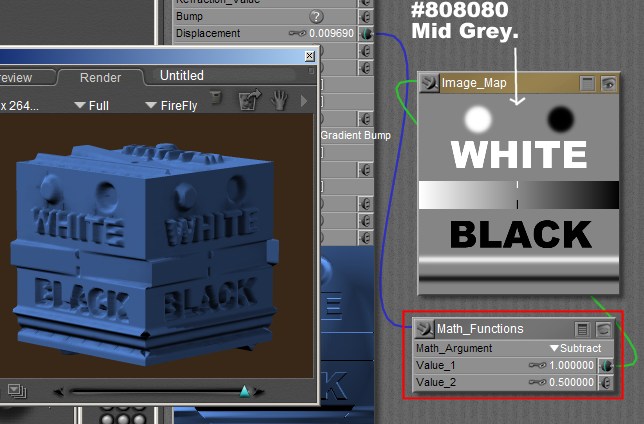
In Poser no displacement is equal to black in the displacement map, and maximum displacement is white. In this set up you would need to have touching edges as black on the map to stop them coming apart.
You can also set the neutral displacement as mid grey (or any other shade) by adding a math node to the shader (see image above). In this set up, touching edges would need to be mid grey in order to stay together.
The hex value for mid grey is #808080, or in RGB each colour would have a value of 128.
lesbentley posted Fri, 05 October 2012 at 4:58 PM

hborre posted Fri, 05 October 2012 at 6:08 PM
Also, in the Pro series, if you are using gamma = 2.2 in the render settings and have not set the gamma = 1 in transparency, bump, and displacement maps, the mesh will be altered causing similar results.
blbarrett posted Fri, 05 October 2012 at 10:11 PM
Well poser has a default smoothing value of 80, and due to some issues loading some models, I've recently reduced the default amount to 15 - much easier to adjust after loading. I never thought about the smoothing check box in the render settings, I'll take a look there... thanks.
Quote - I had gaps in a render at one point, but the folks here pointed out that I was applying "smoothing" to the wrong things, or to the whole scene in the render settings, which causes bad things to happen to sharp edges and corners.
Just in case that was it, and you mistook it for displacement?
blbarrett posted Fri, 05 October 2012 at 10:12 PM
lesbentley - Awesome info, I've been linking my diffuse or black and white bump map into the displacement slot... I had no idea the neutral gray was required.
hborre - another gem I was not aware of, I'll take a look at my scene and see if this applies, thanks.
vilters posted Sat, 06 October 2012 at 4:49 AM
HOLD !
The neutral gray can only be used if you use the Math_Function node with it to MAKE the gray the neutral displacement.
Poser default is BLACK is no displacement
White is displacement.
Poser 1, 2, 3, 4, 5, 7,
P8 and PPro2010, P9 and PP2012, P10 and PP2014 Game
Dev
"Do not drive
faster then your angel can fly"!
blbarrett posted Sat, 06 October 2012 at 5:00 PM
Thanks vilters, I picked up on the math function node.
Still, interested in trying both ways to see which one provides better results, if any.
This Forum ROCKS!
lesbentley posted Mon, 08 October 2012 at 11:04 PM
By all means, try it out for yourself.
If you don't use a maths node to set mid grey as nutral displacement, you can only do positive displacement, bumps but not dents. If you only need positive displacement, then that's OK, no need for the maths node. But some times you may want the displacement to go either way, with some parts going out and other parts going in from the default location of the un-dispalaced surface. With no maths node, the lowest point you can get on the surface will be the altitude of the un-displaced surface. With a maths node the surface can go below its default altitude.
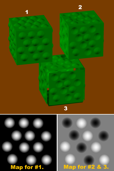
In the image above. #1, with no maths node only positive displacement is possible. #2, with maths node, positive and negative diaplacement. #3, same displacement map as #2, but without maths node results in gaps in cube.
lesbentley posted Mon, 08 October 2012 at 11:10 PM

lesbentley posted Mon, 08 October 2012 at 11:11 PM
lesbentley posted Mon, 08 October 2012 at 11:16 PM

blbarrett posted Tue, 09 October 2012 at 2:10 AM
Thanks for the nice clean write up on this Les.
Very clear and easy to understand, I'll definately give these maps a try.

Zev0 posted Tue, 09 October 2012 at 5:21 PM
Is it better to create a displacement texture that has solid black as Bg or nuetral grey with a math node?
lesbentley posted Tue, 09 October 2012 at 10:30 PM
It depends what you need it to do, sometimes the maths node is extra work that you don't need to do. Neutral grey with a math node is more flexible, because with that set up you can displace the surface in either a positive or negative direction from its default position. Without the maths node, you can only displace the surface in a positive direction.
Black on the map is going to be the the lowest point on the surface (whatever set up you use), and white is going to be the highest point. Without the maths node, any black parts on the map are going to leave the surface in its original position. To make a depression in the surface, you would need to use a colour that was blacker than black, but no colour is blacker than black. That's where the maths node comes in, it "fools" Poser into "thinking" that mid grey on the map is black, and that black on the map is blacker than black.
Not sure if that makes sense, but it's the best explanation I can manage.
If you only need to displace the surface in a positive direction, it's best not to use a maths node. If you want to displace the surface in both positive and negative directions - relative to its initial location - you need a maths node.
vilters posted Wed, 10 October 2012 at 5:27 AM
One extra warning here.
When the figure has a displacement map, it is only calculated at render time.
The cloth room does not "know" that the figure has a displacement map.
The cloth room calculates around the figure object file.
At render time, the displacement map can provoke poking, if the "at render time" calculated dispacement can push through the clothing.
Poser 1, 2, 3, 4, 5, 7,
P8 and PPro2010, P9 and PP2012, P10 and PP2014 Game
Dev
"Do not drive
faster then your angel can fly"!
Zev0 posted Wed, 10 October 2012 at 5:30 AM
Quote - It depends what you need it to do, sometimes the maths node is extra work that you don't need to do. Neutral grey with a math node is more flexible, because with that set up you can displace the surface in either a positive or negative direction from its default position. Without the maths node, you can only displace the surface in a positive direction.
Black on the map is going to be the the lowest point on the surface (whatever set up you use), and white is going to be the highest point. Without the maths node, any black parts on the map are going to leave the surface in its original position. To make a depression in the surface, you would need to use a colour that was blacker than black, but no colour is blacker than black. That's where the maths node comes in, it "fools" Poser into "thinking" that mid grey on the map is black, and that black on the map is blacker than black.
Not sure if that makes sense, but it's the best explanation I can manage.
If you only need to displace the surface in a positive direction, it's best not to use a maths node. If you want to displace the surface in both positive and negative directions - relative to its initial location - you need a maths node.
makes perfect sense..

dnstuefloten posted Wed, 10 October 2012 at 11:01 AM
Wow...lots of fascinating information here! I'll have to start experimenting....
Poser Pro 2014
My personal website:
Novels, photos, video, sculptures and more
Evidence of a Lost
City: An animated movie and novel, in progress
Hag: A novel and live-action movie
blbarrett posted Wed, 10 October 2012 at 11:11 AM
Quote - #3, same displacement map as #2, but without maths node results in gaps in cube.
lesbentley- this is what was causing the issue I started this thread with.
I opened the scene last night and added the math node...... problem solved
**Thanks to everyone for all the great and helpful responses!
**