
Becco_UK opened this issue on Jan 17, 2010 · 38 posts
Becco_UK posted Sun, 17 January 2010 at 4:12 AM
I recently started making a Dalek (2005) version from the Dr Who BBC TV program http://www.bbc.co.uk/doctorwho/
Plans being used are by John Darly and are available as a free pdf download from the Project Dalek site http://www.projectdalek.co.uk/
Cinema4D 9.6 being used for modelling and Maxwell Render 1.7 for the rendering.
Becco_UK posted Sun, 17 January 2010 at 4:15 AM

Becco_UK posted Sun, 17 January 2010 at 4:16 AM
Becco_UK posted Sun, 17 January 2010 at 4:18 AM
Becco_UK posted Sun, 17 January 2010 at 4:19 AM
Becco_UK posted Sun, 17 January 2010 at 4:20 AM

Becco_UK posted Sun, 17 January 2010 at 4:24 AM
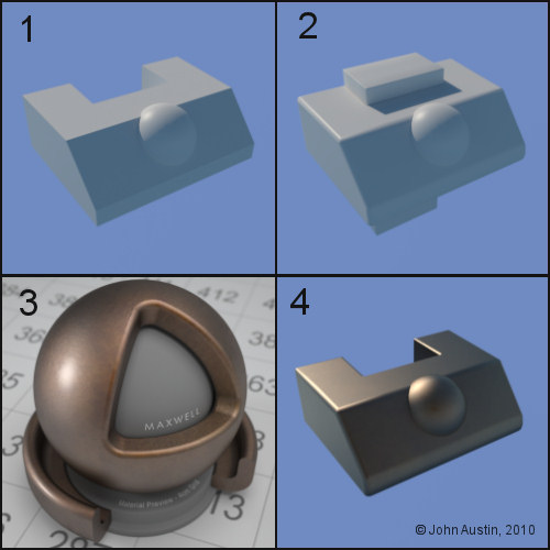
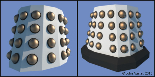
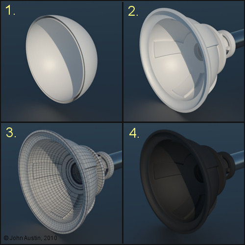
1: Started with a modified cube and hemisphere.
2: Those two parts were connected into a single object, polygon selections made and UV mapped.
3: I use Maxwell Render materials and there are many free ones to use as a starting point
4: Not too bothered with materials yet but in the downloaded bronze one I've added 5% gold Index of Refraction (IOR) data just to give the metalic appearance a boost. Solid materials have IOR values that affect how virtual light interacts with the surface. Using IOR data usually increases ( but not always!) the realistic appearance of a 3d model at render time.
Becco_UK posted Sun, 17 January 2010 at 4:25 AM
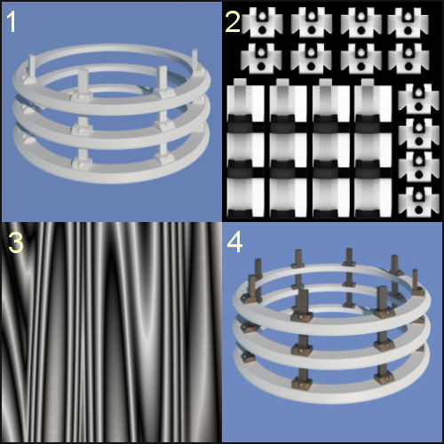
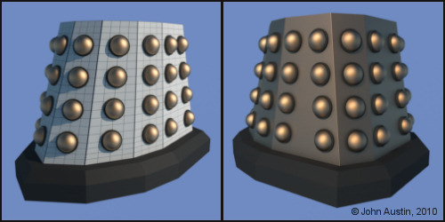
1. I UV mapped an upright and then made copies of this and the blocks using a radial array tool. I only require one half so the radial arrays were made editable and excess objects deleted. I ended up with four uprights and twelve blocks. These parts were connected into a single object. Because the individual parts had already been UV mapped it was quick to form a new UV map of the connected parts.
2. Ambient Occlusion map was baked - these image can be used for a variety of things ie: layer weight, reflection properties, surface roughness etc.
3. I generated a monochrome wood texture using the free Wood Workshop from Spiral Graphics - http://www.spiralgraphics.biz/ This map is being used as a texture layer (reduced opacity soft light setting) on the uprights to give some colour variation to those parts.
4. The uprights and blocks assembly was copied using a Cinema4D instance (Maxwell renders those without any increase to poly' count at render time).
Becco_UK posted Sun, 17 January 2010 at 4:27 AM
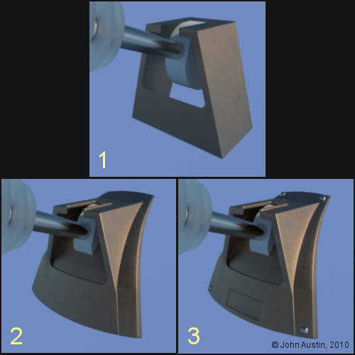
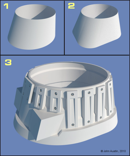
1. I started the 'inner' box of the cowl by modifying a cube.
2. The inner box was given some thickness and a section of mesh was split from the dome to form the cowl base. Selective bevelling was done - no need to waste polygons bevelling edges that will not be typically seen in renders. The inner box and base were joined using a boole tool and tidied up by hand. Also, this part is to be UV mapped and textured with the rest of the dome.
3. The joined edges were bevelled and some detail added to the cowl. I will leave this part as it is for now - probably make some alterations as the Dalek model progresses.
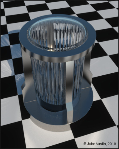
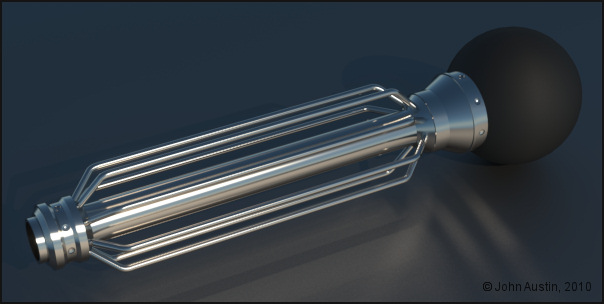
The eye stem is using a Maxwell platinum IOR based material. Perhaps not strictly correct but I like how this metal looks at render time. The alloys look far too 'clean' and bright for my taste.
The eye stem discs use a Maxwell glass material with refraction value set to something suitable for acrylic and a high level of surface roughness added to give the frosted appearance.
Becco_UK posted Sun, 17 January 2010 at 4:29 AM
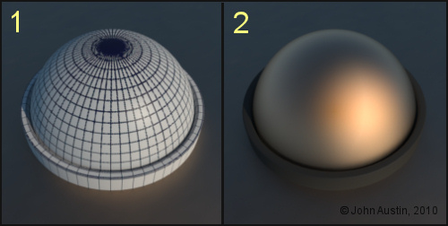
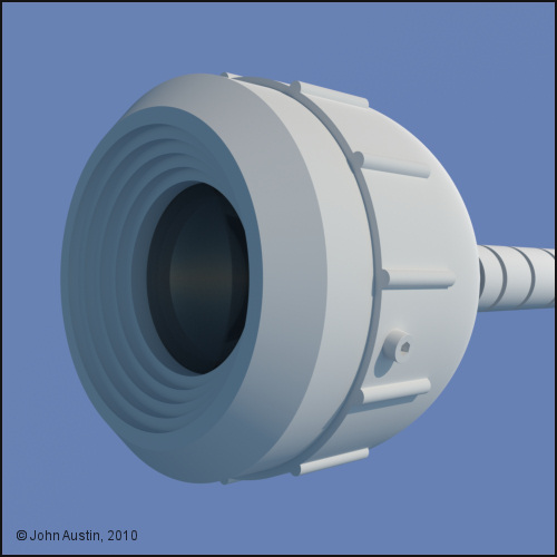
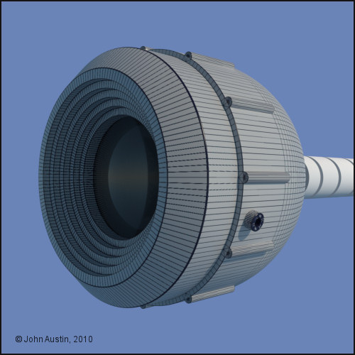
1. A Cinema4D hemisphere and tube were modified and polygon selection tags created for each of the two parts. Connected into a single object and UV mapped. An ambient occlusion texture was created.
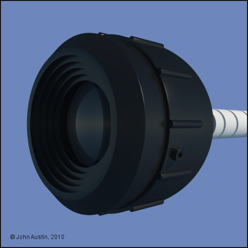
2. First go at a gold material that makes use of a soft edged mottled colour (yellows and oranges) for the first Maxwell material layer. The ambient occlusion bake was used to control two colours of 'dirt' - lightish grey for the rubber seal and vey dark brown for the gold material. The reflective colour of the Maxwell gold material is more or less a uniform medium orange. A small amount (5%) of Gold IOR data was added to the gold material. The Maxwell 'rubber' material uses the same texture map but is constructed much more simple - dark grey colour on the texture map and a 10% overall sheen. The two materials (gold and rubber) on one object are controlled with the polygon selection tags. As with other Dalek materials these will be modified during development of the dalek model.
A further three of these hemispere_seals will be copied and give their own texture maps - those will be instanced randomly over the skirt panels to reduce uniformity of how they look. That's for another time though.
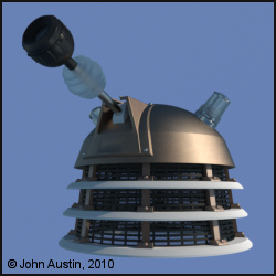
Becco_UK posted Sun, 17 January 2010 at 4:32 AM
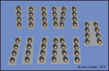
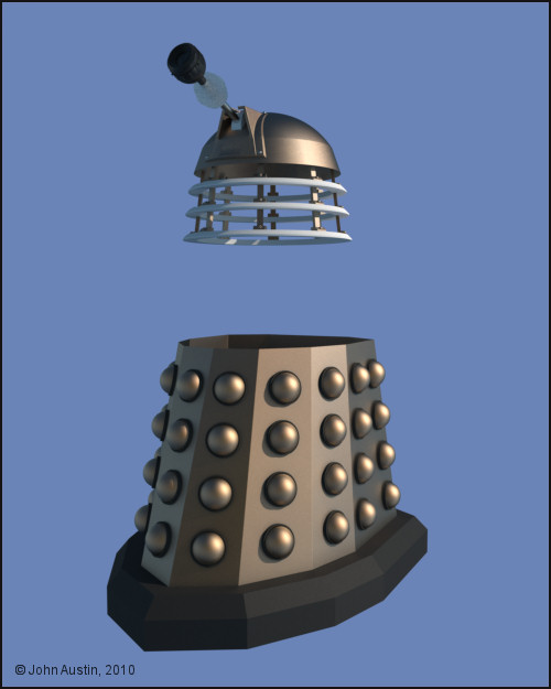
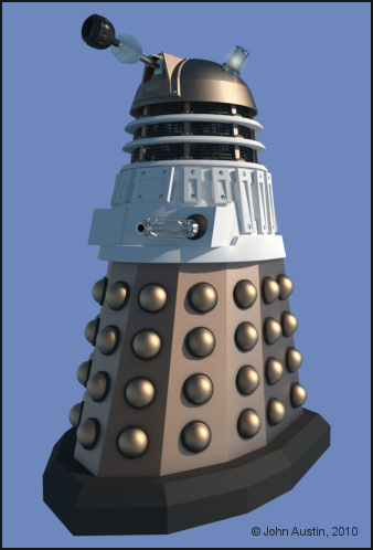
There are only 4 actual hemisphere assemblies being used, instanced and randomly placed on the panels. I will be making another three texture maps to give the hemispheres some variation. The advantage of using instanced objects is at render time. Without instances enabled there are 144,730 polygons at render time in this preview render. Turning on Maxwells true instance system reduced polygon count to 10,570. Quite a saving on Polygon count at render time.
Becco_UK posted Sun, 17 January 2010 at 4:34 AM
The base has also been started but the next bit I will do is to UV map and texture the skirt.
Becco_UK posted Sun, 17 January 2010 at 4:35 AM
Becco_UK posted Sun, 17 January 2010 at 4:36 AM
Becco_UK posted Sun, 17 January 2010 at 4:38 AM
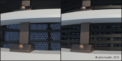
The 'Heronrib' was a bit more involved - each horizontal ring is a spline in a Cinema4D lathe nurbs tool. The reason for using this method is that I wanted to make a texture map - using a lathed spline creates useable UV's automatically.
A simple texture map was made for one ring, ambient occlusion baked to control some light coloured 'dirt' and that texture was used on all the other 'rings'. Each ring was slightly rotated around various axis points to vary how they look instead of each one being perfectly horizontal. The upright parts are just modified cubes in a radial array tool.
Becco_UK posted Sun, 17 January 2010 at 4:39 AM
Becco_UK posted Sun, 17 January 2010 at 4:40 AM
Becco_UK posted Sun, 17 January 2010 at 4:41 AM

airflamesred posted Sun, 17 January 2010 at 4:55 AM
very nice

Khai-J-Bach posted Sun, 17 January 2010 at 3:11 PM
oh very very nice..
a straight build or will there be variants later? (I'd love to see a modern SWD.....)

FarawayPictures posted Mon, 18 January 2010 at 2:00 AM
Becco's making a Dalek!!!!
This I gotta see.
Becco_UK posted Wed, 20 January 2010 at 5:54 PM
Kaibach: Thank you. I will probabbly just make the new series dalek (2005 for now). Waiting for the weather to improve here so that I can carry on with the Joe 90 Explosives truck dual project. I could have carried on with the 3d version but I would sooner have the real model running roughly along side progress of the 3D version.
FarawayPictures: I've been meaning to start this Dalek since last year but the Eagle model consumed too much spare time. I've seen your nice Dalek in your gallery too.
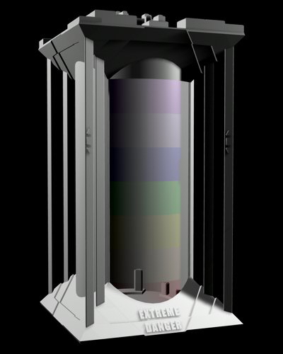
Anyway, I've given the Dalek a rest for a few days so that I could work on possible Dalek scene props - I've started by finding my old (2004) Extreme Danger prop.
Becco_UK posted Wed, 20 January 2010 at 5:56 PM
Becco_UK posted Wed, 20 January 2010 at 5:58 PM
Becco_UK posted Sun, 24 January 2010 at 12:51 PM
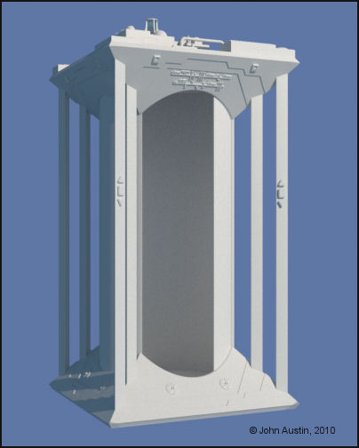
1. An elipse shaped spline lofted into a circle spline. This was later made editable and the rear polygons deleted.
2. A rounded square spline lofted into a circle spline. This was later made editable and the front polygons deleted.
3. The two polygon halves from step 1 and 2 joined together. Knife cuts and extrusions made. Two dummy' gun boxes were added to help with forming the main shoulder. Some slats in their early stages of development added. This section has been the most challenging so far.
FarawayPictures posted Mon, 25 January 2010 at 1:49 AM
Superb. This was the part I found the hardest when I made mine. Still not that happy with it and want to go back someday and have another crack at it.
Looks like you nailed it!
Becco_UK posted Mon, 25 January 2010 at 4:30 AM
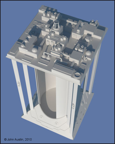
A look at all the Dalek as it was this morning.
airflamesred posted Mon, 25 January 2010 at 5:22 AM
Nice becco
I might be being a bit dumb here but where does mesh 2 appear in mesh 3. I'm guessing by your description that its the inside
Becco_UK posted Mon, 25 January 2010 at 6:14 AM
airflamesred: Thank you. The mesh in image 2 formed the rear polygons of the shoulder. Image 3 is the two meshes joined together.
airflamesred posted Mon, 25 January 2010 at 6:27 AM
got ya
always interested in other folks workflow
Becco_UK posted Mon, 25 January 2010 at 7:48 AM
airflamesred: I don't always explain things clearly enough to start with :-)
Becco_UK posted Wed, 27 January 2010 at 5:58 PM
1. Start with a couple of hemispheres.
2. Followed by some welding, extrusions and bevelling. Detail parts added.
3. UV mapped.
4. Ambient occlusion baked as texture - used to control a light coloured 'dirt' texture layer.
FarawayPictures posted Thu, 28 January 2010 at 1:52 AM
Who was that comedian who used to take the mick out of the Daleks, saying 'Extermination or Plumbing?'
Looking good.

billy-home posted Thu, 28 January 2010 at 3:16 PM
I've been following this over at Project Dalek, your doing a fantastic job on this mate, very well done indeed
Becco_UK posted Wed, 03 February 2010 at 3:55 AM
billy-home: Thank you. I discovered the Project Dalek site and its forums sometime last year - it's a great reference place for anyone with an interest in Daleks. I think better 3d models can be made if we take some time to learn and understand how the real thing is made.
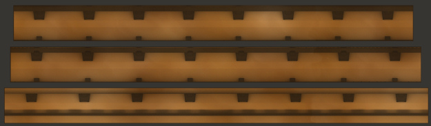
Back to this Dalek. I'm UV mapping with Bodypaint as I go along and the neck rings were the next bits. These were originally made from modified Cinema tube primitives and some bevelling of edges. The problem with that method of construction comes at the texturing stage - by time the tube has been modified etc the UV's are messy and so much time can be wasted making useable UV maps.
So, once I was happy with the three neck rings I selected the rear loop of edges of a ring, used Cinemas edge to spline and 'lathed' the spline. That takes aonly a few seconds to do. Repeated this for the remaining couple of rings which left three lathed spline assemblies. Each was made editable and a polygon selection tag created for each of the rings. The three rings were connected into a single object and work in Bodypaint was then straight forward with only some scaling of UV's really required. Takes longer to write about than do!
The reduced size texture map is how the UV's translated into the texture - much nicer than leaving Cinema4D to its own devices.
Becco_UK posted Wed, 03 February 2010 at 3:58 AM
FarawayPictures posted Thu, 04 February 2010 at 2:26 AM
billy-home posted Thu, 04 February 2010 at 4:46 PM
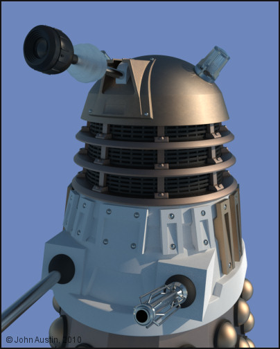
They look like they each have a couple of extra hemispheres more than the usual Dalek, but who's complaining
